Electronic beacon for a localization system

a technology of localization system and electronic beacon, which is applied in the field of electronic beacon, can solve the problems of reducing the performance of other wireless applications, and increasing the rf noise level, so as to reduce the contribution of the beacon to the rf noise, reduce the transmitting of the localizing beacon signal, and reduce the power use of the beacon

Active Publication Date: 2021-09-16
SIGNIFY HLDG BV
View PDF0 Cites 0 Cited by
  • Summary
  • Abstract
  • Description
  • Claims
  • Application Information

AI Technical Summary

Benefits of technology

[0008]There is a desire to address these problems and other problems identified herein. The beacon defined in the claims switches a radio circuit mode to active mode to periodically transmit the localizing beacon signal through the radio circuit, or switches the radio circuit mode to reduced-energy mode to reduce transmitting of the localizing beacon signal, in dependency on the occupancy signal. In this way both the power use of the beacon is reduced and the beacon's contribution to the RF noise is reduced. On the other hand, the quality of the localization system is not or little impacted as the reduction of transmitting of the localizing beacon signal depends on an occupancy signal so that occupied areas continue to have access to the localization signal, e.g., to obtain localization services.
[0009]In an embodiment, a processor circuit is configured with a first repetition rate and a second repetition rate, the processor circuit transmitting the localizing beacon signal at the first repetition rate in the active mode and at the second repetition rate in the reduced-energy mode, the second repetition rate being lower than the first repetition rate. In this way, localization continues to work for stationary objects, while localization for non-stationary objects continues to get localization signals at a higher repetition rate, e.g., a repetition rate sufficient to track the moving object.
[0010]A repetition rate is the frequency with which the localizing beacon signal is repeated. This frequency is not to be confused with the beacon transmission radio frequency. With a lower repetition rate, the pauses between transmission are extended to lower energy consumption. Repetition rate may be expressed as a number of transmissions per second, or as the time between two subsequent transmissions, etc.

Problems solved by technology

Another drawback of current beacon technology is that they increase the RF noise level.
Moreover, as the beacon signal may not penetrate evenly—or at all—throughout a building, multiple beacons may have to be scattered throughout a building.
All of these beacons transmit wireless signals interminably which leads to an increase in the RF noise level.
Potentially this decreases the performance of other wireless applications.

Method used


Image

  • Electronic beacon for a localization system
  • Electronic beacon for a localization system
  • Electronic beacon for a localization system

Examples


Embodiment Construction

[0054]While this invention is susceptible of embodiment in many different forms, there are shown in the drawings and will herein be described in detail one or more specific embodiments, with the understanding that the present disclosure is to be considered as exemplary of the principles of the invention and not intended to limit the invention to the specific embodiments shown and described.

[0055]In the following, for the sake of understanding, elements of embodiments are described in operation. However, it will be apparent that the respective elements are arranged to perform the functions being described as performed by them. Further, the invention is not limited to the embodiments, and the invention lies in each and every novel feature or combination of features described herein or recited in mutually different dependent claims.

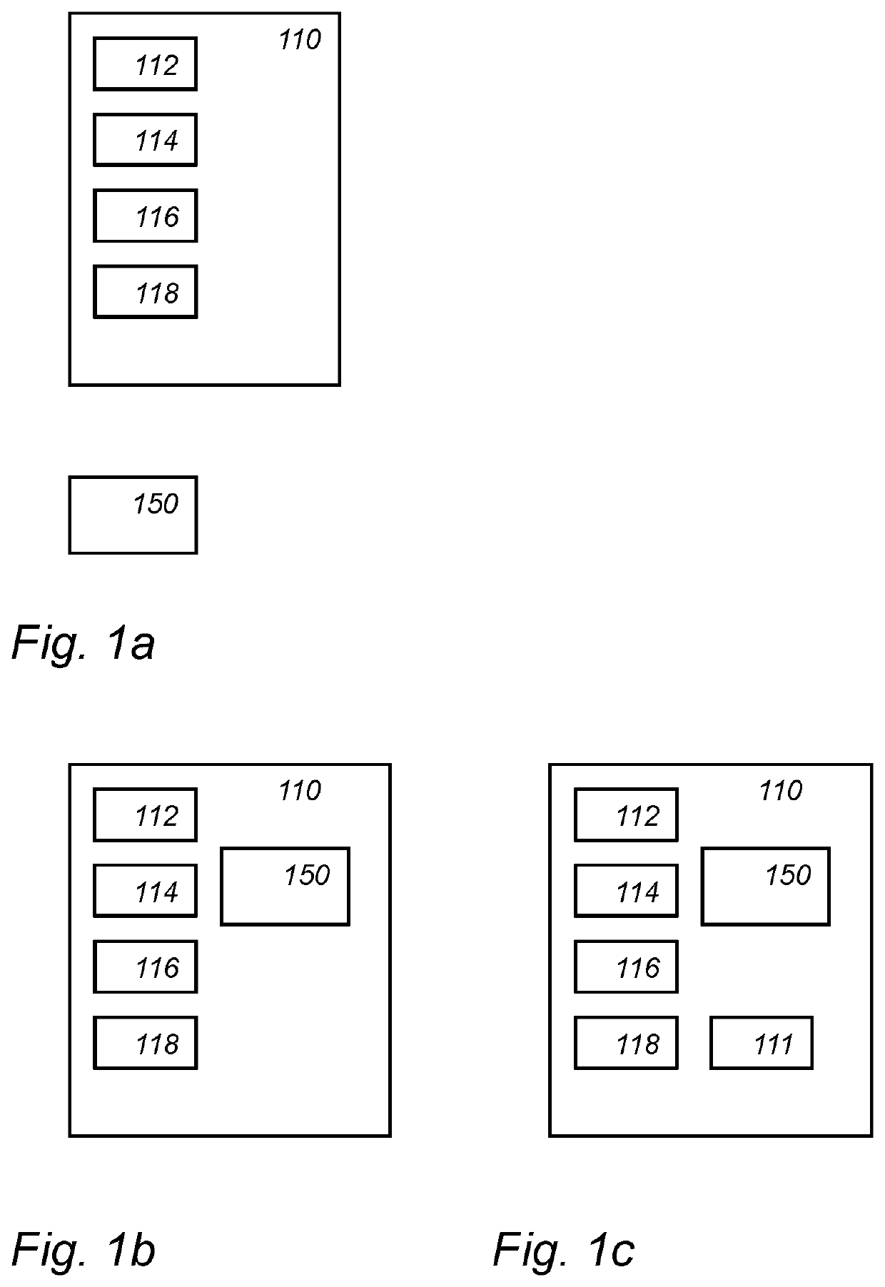
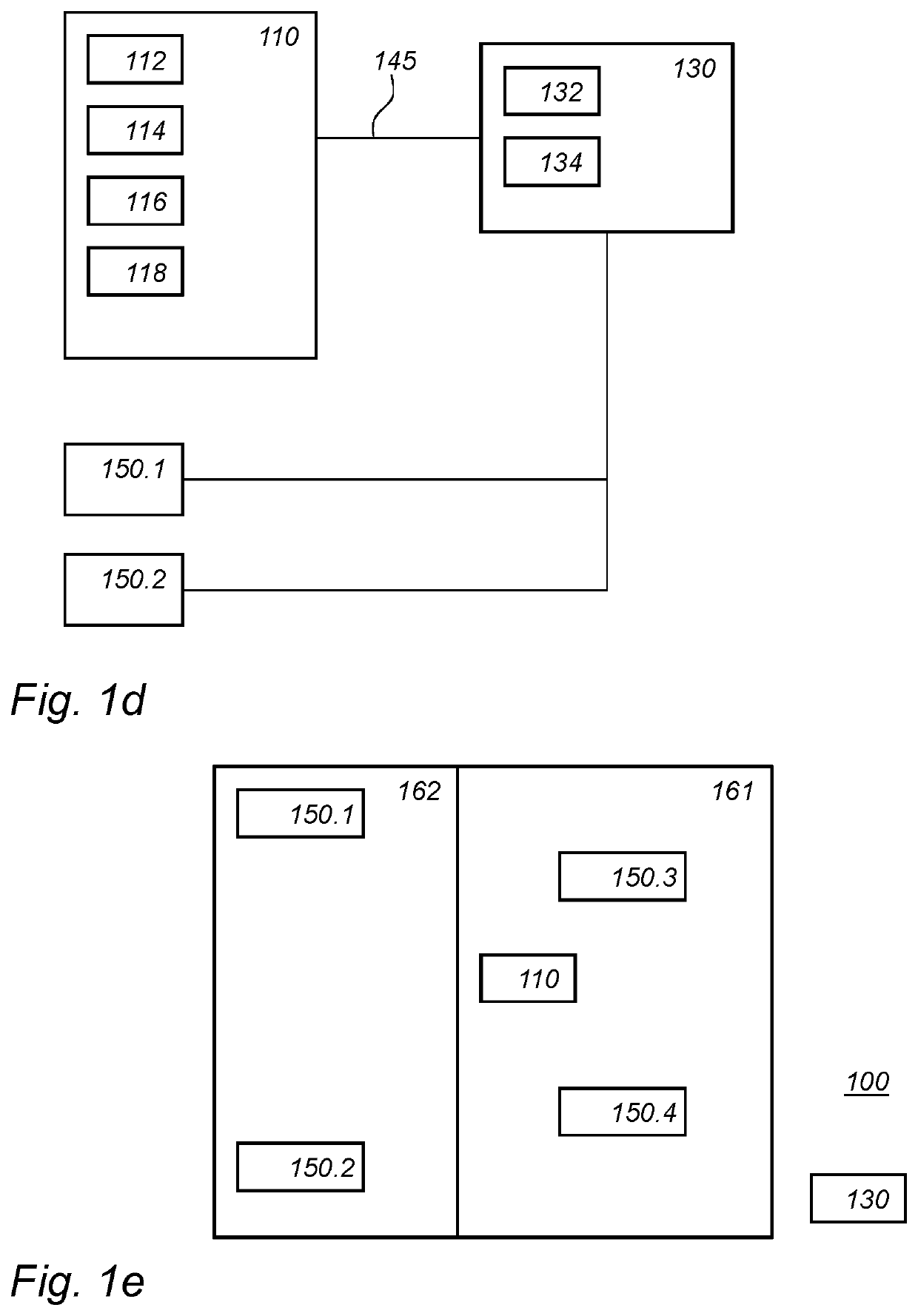
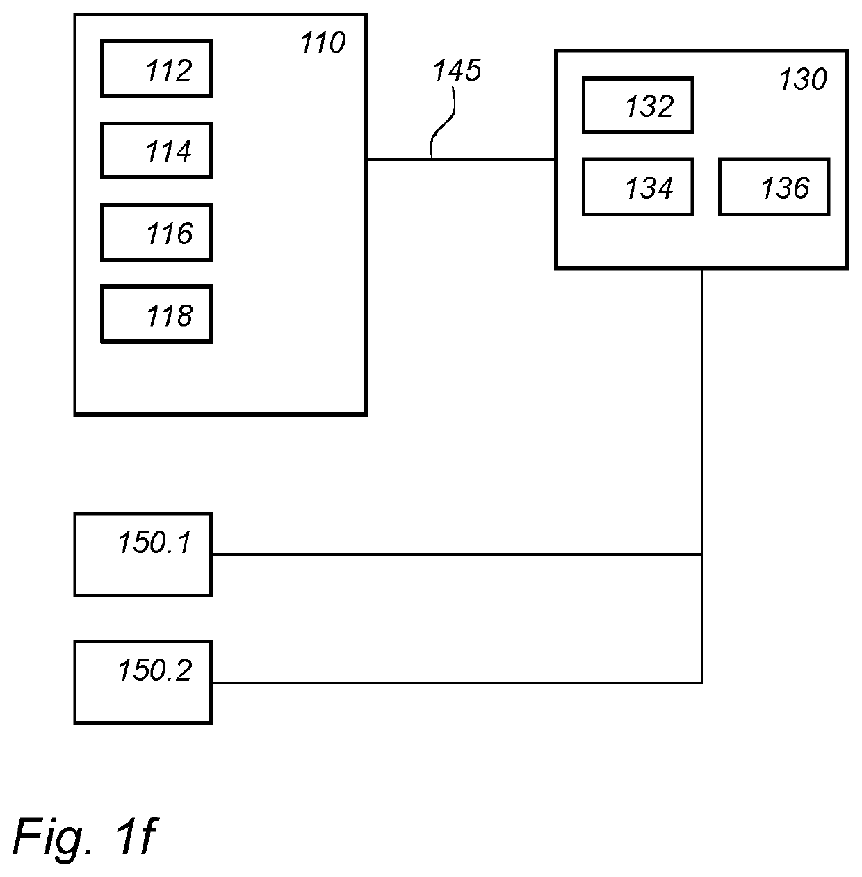
[0056]FIG. 1a schematically shows an example of an embodiment of a beacon 110. Beacon 110 can form a localization system together with a number of other bea...


PUM


Abstract

A beacon is provided comprising a processor circuit configured to, in dependency on an occupancy signal, switch the radio circuit mode to active mode and periodically transmit the localizing beacon signal through the radio circuit, or switch the radio circuit mode to reduced-energy mode and reduce transmitting of the localizing beacon signal.

Description

FIELD OF THE INVENTION[0001]The invention relates to an electronic beacon, a control device, a localization system, an electronic beacon method, a control method, and a computer readable medium.BACKGROUND[0002]Location based services are increasingly used. For outdoor applications, such as maps and navigation on a mobile phone, the current location of the mobile phone is used to provide the service. For example, outdoors application may use a GPS receiver to obtain coordinates.[0003]Also indoors, there is an increasing desire to have localization information available, e.g., on mobile devices such as mobile phones. The indoor localization can be used for applications ranging, e.g., from indoor navigation to provide contextual services. For example, in a museum an application may provide context specific information depending on the current location of the mobile device; for example, the information may relate to a painting that is currently close to the device. For example, in a sho...

Claims


Application Information

Patent Timeline
Patent Type & Authority Applications(United States)
IPC IPC(8): H04W64/00H04W52/02G01S1/04G01S5/14
CPCH04W64/003H04W52/0216H04W52/0274G01S1/042H04W52/0251H04W76/28Y02D30/70
Inventor WENDT, MATTHIASDEIXLER, PETERRADERMACHER, HARALD JOSEF GÜNTHER
Owner SIGNIFY HLDG BV
Why Eureka
Try Eureka