

Elastic bandage with engagement means
- Summary
- Abstract
- Description
- Claims
- Application Information
AI Technical Summary
Benefits of technology
Problems solved by technology
Method used
Image

Examples
Embodiment Construction
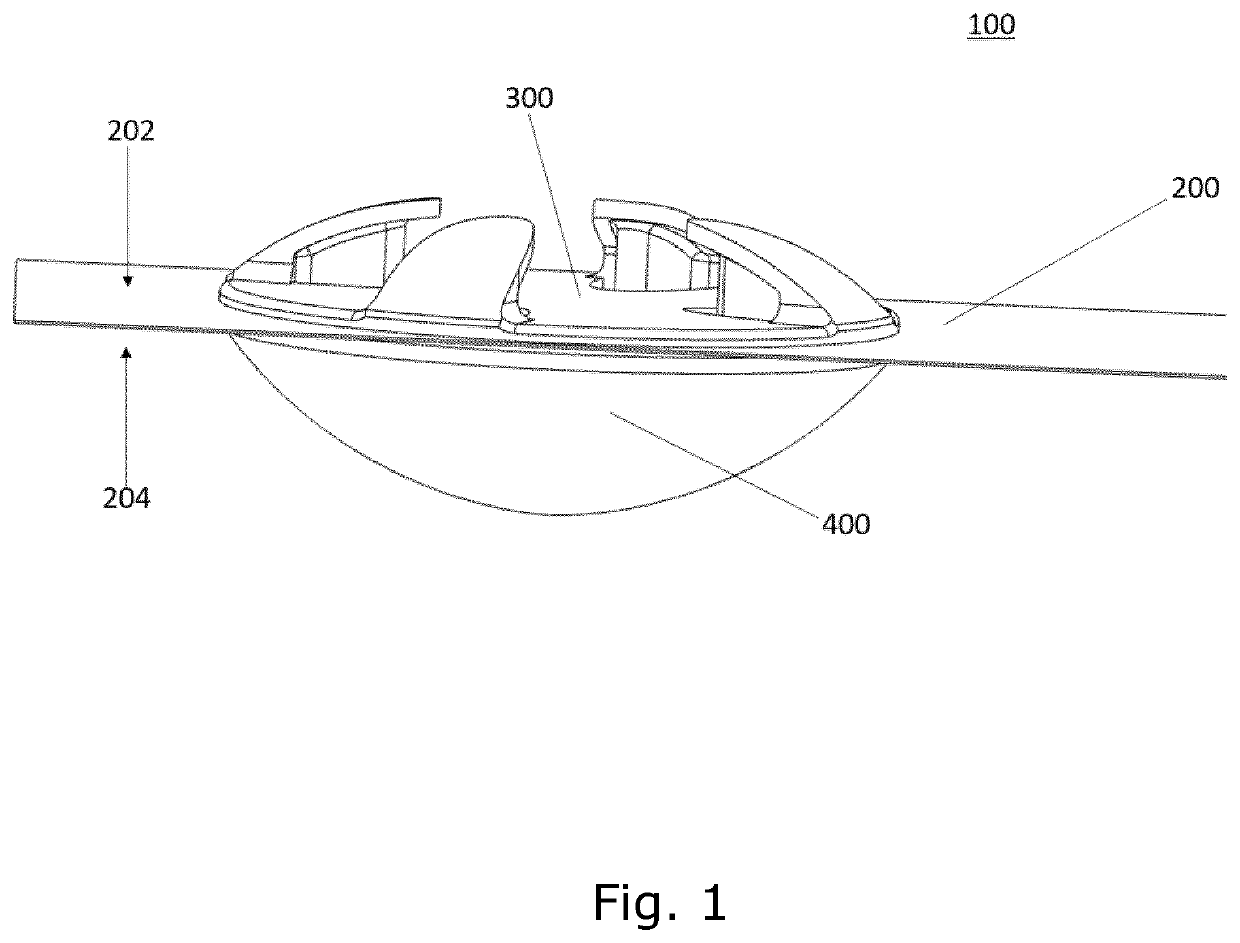
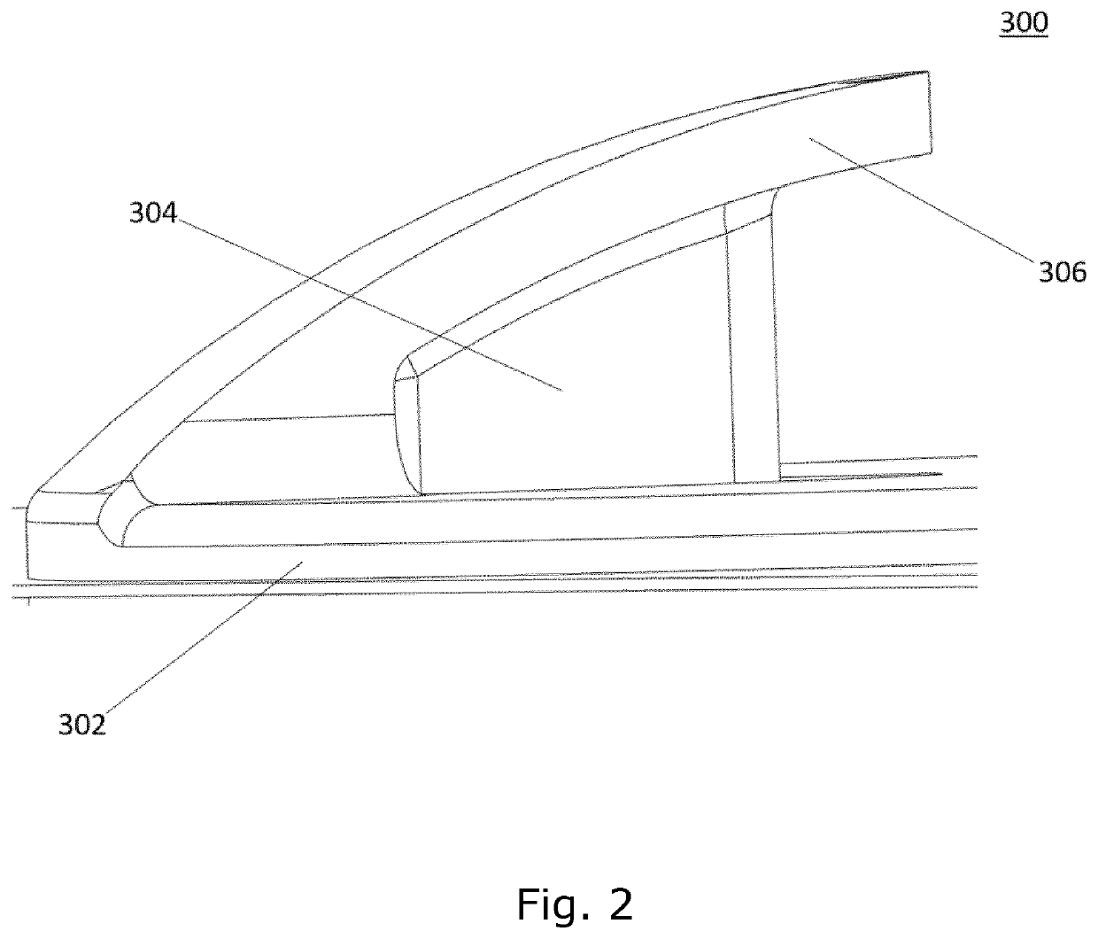
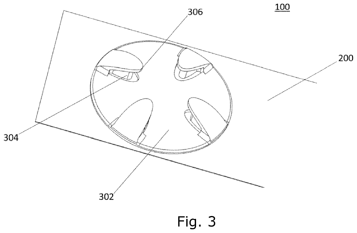
[0005]One aspect of the present invention relates to an elastic bandage, comprising: an elastic, elongated material having an elongated length substantially longer than a width of the material; wherein the elastic bandage further comprises an engagement means joined to a first side surface of the elongated material, and being sized and adapted for the elongated material to be pulled around.
[0006]Another aspect of the present invention relates to an elastic bandage, comprising:
an elastic, elongated material having an elongated length substantially longer than a width of the material; wherein the elastic bandage further comprises an engagement means joined to a first side surface of the elongated material, and being sized and adapted for the elongated material to be pulled around during use of the elastic bandage.
[0007]Yet another aspect relates to an elastic bandage, comprising:
an elastic, elongated material having an elongated length substantially longer than a width of the material...
PUM
 Abstract
Description
Claims
Application Information