Terminal apparatus and base station apparatus

a terminal and base station technology, applied in the direction of transmission path sub-channel allocation, transmission path division, wireless communication, etc., can solve the problems of increasing the delay of scheduled access, increasing the amount of control information used, and introducing mmtc, so as to achieve efficient uplink data transmission

Pending Publication Date: 2021-09-23
SHARP KK +1
View PDF3 Cites 19 Cited by
  • Summary
  • Abstract
  • Description
  • Claims
  • Application Information

AI Technical Summary

Benefits of technology

[0022]According to one or more aspects of the present invention, efficient uplink data transmission can be achieved.

Problems solved by technology

In 5G, Internet of Things (loT) is expected to be established that allows connection of various types of equipment not previously connected to a network, and establishment of mMTC is an important issue.
5G rnMTC includes a problem in that the use of the scheduled access increases the amount of control information.
URLLC includes a problem in that the use of the scheduled access increases delay.

Method used


Image

  • Terminal apparatus and base station apparatus
  • Terminal apparatus and base station apparatus
  • Terminal apparatus and base station apparatus

Examples


first embodiment

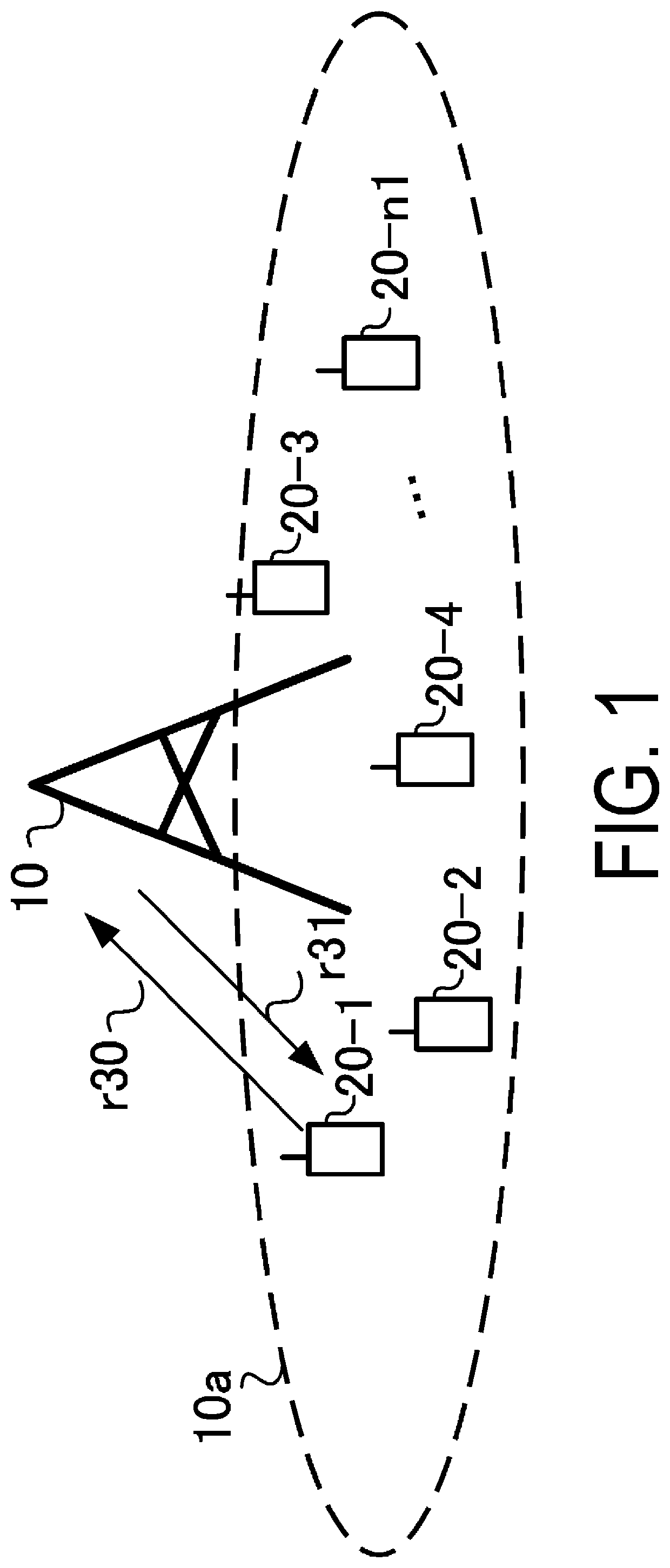
[0040]FIG. 1 is a diagram illustrating an example of a configuration of a communication system according to the present embodiment. The communication system according to the present embodiment includes a base station apparatus 10 and terminal apparatuses 20-1 to 20-n1 (n1 is a number of terminal apparatuses connected to the base station apparatus 10). The terminal apparatuses 20-1 and 20-n1 are also collectively referred to as terminal apparatuses 20. Coverage 10a is a range (a communication area) in which the base station apparatus 10 can connect to the terminal apparatus 20 (coverage 10a is also referred to as a cell).

[0041]In FIG. 1, an uplink radio communication r30 at least includes the following uplink physical channels. The uplink physical channels are used for transmitting information output from a higher layer.[0042]Physical Uplink Control Channel (PUCCH)[0043]Physical Uplink Shared Channel (PUSCH)[0044]Physical Random Access Channel (PRACH)

[0045]The PUCCH is a physical cha...

second embodiment

[0171]The present embodiment describes a method for specifying switching to multiple BWPs with no change in the number of information bits in the DCI format satisfying high reliability. A communication system according to the present embodiment includes the base station apparatus 10 and the terminal apparatus 20 described with reference to FIG. 3, FIG. 4, FIG. 5, and FIG. 6. Differences from / additions to the first embodiment will be mainly described below.

[0172]As a method for specifying BWPs to be used for data transmission for URLLC, the base station apparatus utilizes one or both of the RRC information and the Compact DCI format to configure scheduling of the data transmission for URLLC. In particular, the RNTIs during scheduling in accordance with the Compact DCI format are designated by configuration of the PDCCH (PDCCH-config) or configuration of the PDSCH (PDSCH-config) for configuration for each downlink BWP (BWP-Downlink) for configuration of the serving cell (ServingCellCo...

third embodiment

[0177]The present embodiment describes a method for notifying a request for switching to the BWP in accordance with the uplink control information. A communication system according to the present embodiment includes the base station apparatus 10 and the terminal apparatus 20 described with reference to FIG. 3, FIG. 4, FIG. 5, and FIG. 6. Differences from / additions to the previous embodiments will be mainly described below.

[0178]Description is given using a sequence chart of FIG. 7. In S203, the terminal apparatus receives SR resource configuration information requesting BWP switching and SR resource configuration information not requesting BWP switching. In a case that data that is not URLLC is generated, the terminal apparatus generates an SR signal in a specified PUCCH format based on the SR configuration not requesting BWP switching (S204). Here, the uplink data that is not URLLC being generated may refer to providing a transport block of data for which the higher layer is not UR...


PUM


Abstract

A base station apparatus, a terminal apparatus, and a communication method are provided that can distinguish eMBB traffic from URLLC traffic in an uplink. A control information detection unit configured to detect RRC and first DCI or second DCI and a transmitter configured to perform one of first data transmission and second data transmission are included, wherein at least two BPWs are configured for a serving cell, only one of the at least two BWPs is activated, a BWP-specific configuration included in the RRC enables the second DCI to configure second data transmission based on the configuration, first data transmission notified in first DCI transmits data allows data to be transmitted in an active BWP, second data transmission notified in second DCI allows data to be transmitted in the BWP configured with the second data transmission, and in a case that the second DCI is detected and that the BWP configured with the second data transmission is deactivated, the BWP configured with the second data transmission is configured to be activate.

Description

TECHNICAL FIELD[0001]The present invention relates to a base station apparatus, a terminal apparatus, and a communication method for these apparatuses. This application claims priority based on Japanese Patent Application No. 2018-148469 filed in Japan on Aug. 7, 2018, the contents of which are incorporated herein by reference.BACKGROUND ART[0002]In recent years, 5th Generation (5G) mobile telecommunication systems have been focused on, and a communication technology is expected to be specified, the technology establishing MTC mainly based on a large number of terminal apparatuses (Massive Machine Type Communications; mMTC), Ultra-reliable and low latency communications (URLLC), and enhanced Mobile BroadBand (eMBB). The 3rd Generation Partnership Project (3GPP) has been studying New Radio (NR) as a 5G communication technique and discussing NR Multiple Access (MA).[0003]In 5G, Internet of Things (loT) is expected to be established that allows connection of various types of equipment ...

Claims


Application Information

Patent Timeline
Patent Type & Authority Applications(United States)
IPC IPC(8): H04W72/12H04L1/18
CPCH04W72/1278H04W72/14H04L1/1812H04L1/1822H04L1/1851H04L1/1819H04L1/1896H04L1/0041H04L1/0045H04L5/0053H04L5/0094H04L5/001H04L5/0098H04W72/0453H04W72/23H04W72/20
Inventor NAMBA, HIDEOGOTO, JUNGONAKAMURA, OSAMU
Owner SHARP KK
Why Eureka
Try Eureka