Calibration of an optical detector using a micro-flow chamber

a micro-flow chamber and optical detector technology, applied in the field of smoke detectors, can solve the problems of cumbersome process, time-consuming, and inability to fully automate the process

Pending Publication Date: 2021-09-30
CARRIER CORP
View PDF2 Cites 2 Cited by
  • Summary
  • Abstract
  • Description
  • Claims
  • Application Information

AI Technical Summary

Benefits of technology

[0024]In addition to one or more of the features described above, or as an alternative, in further embodiments the detector includes at least one sensing volume, and the internal chamber of the housing is sized to extend through the at least one sensing volume.
[0025]In addition to one or more of the features described above, or as an alternative, in further embodiments a first surface of the housing is positionable in direct contact with a sensing surface of the detector, the first surface having a contour complementary to the sensing surface of the detector.
[0026]In addition to one or more of the features described above, or as an alternative, in further embodiments the at leas

Problems solved by technology

This process is cumbersome, time co

Method used


Image

  • Calibration of an optical detector using a micro-flow chamber
  • Calibration of an optical detector using a micro-flow chamber
  • Calibration of an optical detector using a micro-flow chamber

Examples


Embodiment Construction

[0038]A detailed description of one or more embodiments of the disclosed apparatus and method are presented herein by way of exemplification and not limitation with reference to the Figures.

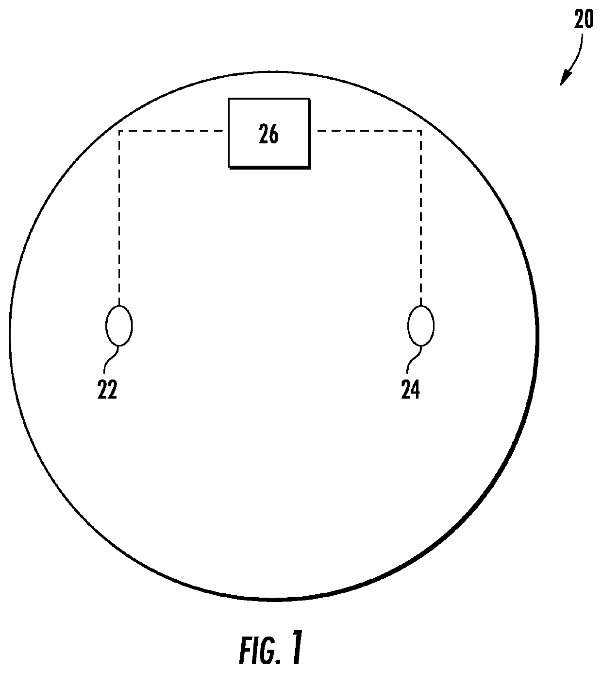
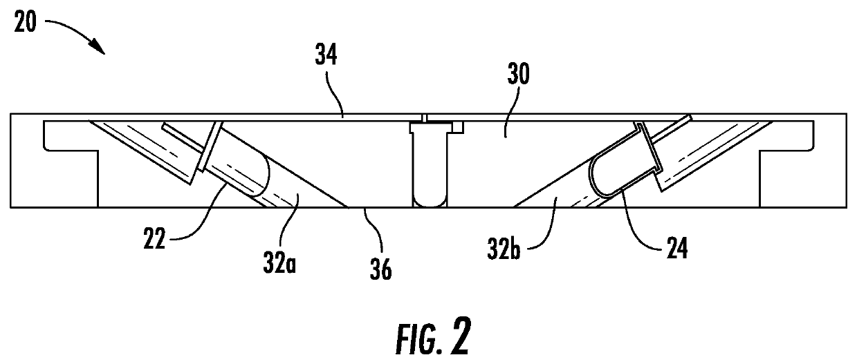
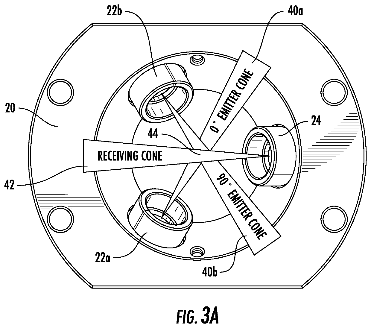
[0039]Referring now to the FIGS., an example of an optical detector 20 for detecting one or more conditions or events within a designated area to be monitored is illustrated. In the illustrated, non-limiting embodiment, the optical detector 20 is a chamber-less smoke detector. However, it should be understood that the optical detector 20 illustrated and described herein is intended as an example only and that other types of detectors, such as chambered optical detectors and duct detectors, are also contemplated herein.

[0040]It will be appreciated that a chamber-less smoke detector, where smoke is detected in the ambient adjacent to and outside of the detector rather than in a chamber within the body of the detector (as in a chambered detector), may provide additional benefits including, but not l...


PUM


Abstract

A method of calibrating an optical detector includes installing a calibration system within at least one sensing volume of the optical detector, filling a chamber of the calibration system with a material to achieve a known obscuration, and measuring an obscuration of the material within the chamber.

Description

CROSS REFERENCE TO RELATED APPLICATIONS[0001]This application claims the benefit of U.S. Application No. 62 / 778,099, filed on Dec. 11, 2018, which is incorporated herein by reference in its entirety.BACKGROUND[0002]Embodiments of the present disclosure described herein generally relate to smoke detectors and, more particularly, to systems and methods for verifying operational integrity of smoke detectors.[0003]Smoke detectors exist including a light source that produces and emits a light beam into an area being monitored. A photo detector is positioned to receive light that is scattered by smoke particles from the area being monitored. A processing circuit is associated with the light source and the photo detector to measure the amount of light received and evaluate whether one or more smoke particles are present.[0004]The various components of the smoke detector contribute to the sensitivity of the detector and as a result, at the time of manufacture, the smoke detector requires ca...

Claims


Application Information

Patent Timeline
IPC IPC(8): G01N21/53G01N21/05
CPCG01N21/53G01N2201/127G01N21/05G01N21/274G01N21/49G08B17/107G08B29/145
Inventor GULER, URCANLINCOLN, DAVID L.
Owner CARRIER CORP
Why Eureka
Try Eureka