Antenna integrating delay lenses in the interior of a distributor based on parallel-plate waveguide dividers

a delay lens and distributor technology, applied in the field of multibeam antennas, can solve the problems of weight, in particular in satellites, and cos

Active Publication Date: 2020-02-04
THALES SA
View PDF7 Cites 1 Cited by
  • Summary
  • Abstract
  • Description
  • Claims
  • Application Information

AI Technical Summary

Benefits of technology

[0013]The invention therefore aims to avoid an oversizing of the distributor and of the radiating aperture along the longitudinal axis of the radiating aperture, due to the waves emitted by input sources that are off-centred with respect to the focal point of the quasi-optical beamformer. The invention also aims, in certain embodiments, to avoid an imperfect focus of off-axis beams.

Problems solved by technology

Thus, the beams have different widths, in particular in the main E- and H-planes of radiation, this being unsatisfactory.
This oversizing 4 of the distributor 1, which leads to an oversizing of the longitudinal radiating horns 5 along the same axis, has a cost in terms of weight, in particular in a satellite.

Method used


Image

  • Antenna integrating delay lenses in the interior of a distributor based on parallel-plate waveguide dividers
  • Antenna integrating delay lenses in the interior of a distributor based on parallel-plate waveguide dividers
  • Antenna integrating delay lenses in the interior of a distributor based on parallel-plate waveguide dividers

Examples


first embodiment

[0042]FIG. 6A illustrates a first embodiment, in which the wave conversion is carried out in the last stage of the distributor 1. The sources 10 emit waves, of cylindrical wave fronts, towards the power distributor 1. The power distributor 1 is composed of a plurality of stages e1, . . . , eN. In the first stage e1, which is directly connected to the sources 10, optionally via a straight 90° bend, a parallel-plate divider 3 composed of two branches B1 and B2 is located. It will be noted that the straight bend does not add any additional length to the beamformer; for this reason straight bends have no impact on the structure. The parallel-plate divider 3 is configured to distribute the electric field E issued from the sources 10. The parallel-plate dividers 3 may be unbalanced in order to modify the division of power and thus to control the distribution of power to the horns 5.

[0043]As illustrated in FIG. 6B, in the last stage of the distributor, at the output of each branch B1, B2 o...

third embodiment

[0050]FIG. 9 illustrates the invention. The sources 10 emit cylindrical waves towards the power distributor 1. The power distributor 1 is composed of a plurality of stages e1, . . . , eN. In the first stage e1, directly connected to the sources 10, optionally via a 90° bend, is located a parallel-plate divider 3 that is composed of two branches B1 and B2. The parallel-plate divider 3 is configured to distribute the electric field E issued from the sources 10.

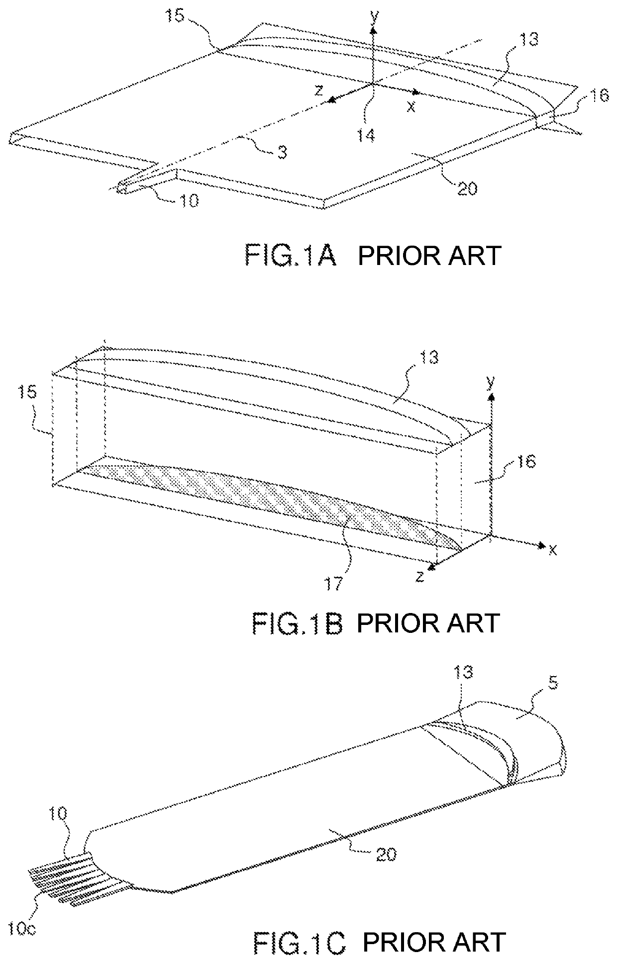
[0051]The lenses implemented in the third embodiment may take the form of straight-profile lenses comprising a protrusion (see FIG. 1B) in each of the branches B1, B2 of each divider. Each of the branches of the stage e1 leads to a divider in a higher stage e2. Thus, a parallel-plate divider 3 is connected to the first branch B1. This divider itself comprises two branches B1 and B2, each of the branches B1 and B2 of this parallel-plate divider 3 also comprising a straight-profile lens 6. The distributor 1 is thus defined by a co...


PUM

PropertyMeasurementUnit
degrees of freedomaaaaaaaaaa
heightsaaaaaaaaaa
electric fieldaaaaaaaaaa

Abstract

A quasi-optical beamformer includes a power distributor composed of a succession of parallel-plate dividers extending in a YZ-plane from a first stage to a last stage, each parallel-plate divider comprising, in each of the stages of the corporate structure located under a higher stage, first and second parallel-plate waveguide branches leading to respective parallel-plate dividers of the following stage of the corporate structure, the beamformer furthermore including a plurality of lenses extending longitudinally along the X-axis in at least one stage of the power distributor, so as to apply a delay that is continuously variable along the X-axis, the lenses being placed in each of the branches of the dividers of at least one stage in the power distributor.

Description

CROSS-REFERENCE TO RELATED APPLICATIONS[0001]This application claims priority to foreign French patent application No. FR 1700799, filed on Jul. 27, 2017, the disclosure of which is incorporated by reference in its entirety.FIELD OF THE INVENTION[0002]The invention relates to a multibeam antenna in particular applied to spatial communications, and intended to be integrated into satellites, or into ground stations. The antenna may irrespectively operate in emission or in reception, in a reciprocal way. In the following description, the multibeam antenna operates in emission.BACKGROUND[0003]Multibeam antennas are commonly used in spatial communications, on board a satellite (transmission of telemetry data, telecommunications), or on the ground (satcom terminal or user terminal of a telecommunications system). Among multibeam antennas, continuous linear radiating aperture antennas using a parallel-plate waveguide beamformer allow a plurality of beams to be formed over a wide angular se...

Claims


Application Information

Patent Timeline
Patent Type & Authority Patents(United States)
IPC IPC(8): H01Q13/00H01Q15/06H01P5/19H01Q21/00H01Q21/06H01Q13/02H01Q3/46H01Q1/28H01Q13/28H01Q5/22
CPCH01Q21/0031H01Q3/46H01P5/19H01Q5/22H01Q13/28H01Q13/02H01Q1/288H01Q21/064H01Q15/06
Inventor TUBAU, SÉGOLÈNELEGAY, HERVÉGIRARD, ETIENNEFRAYSSE, JEAN-PHILIPPE
Owner THALES SA
Why Eureka
Try Eureka