Cooling device for internal combustion engine

A technology of cooling device and internal combustion engine, which is applied to the cooling of the engine, the arrangement of the combination of cooling of the power unit, and the power unit, etc., which can solve the problem of impeding the promotion of warm-up, the inability to fully block the window holes, and the inability to sufficiently prevent the intake of cooling air and other issues to achieve the effect of promoting the warm-up

Active Publication Date: 2013-03-27
HONDA MOTOR CO LTD
View PDF6 Cites 10 Cited by
  • Summary
  • Abstract
  • Description
  • Claims
  • Application Information

AI Technical Summary

Problems solved by technology

[0011] Therefore, at low temperature, the window hole cannot be fully closed, and outside air enters from the gap.
[0012] In addition, since the louver of Patent Document 1 is installed on the recoil starter case, there is a gap originally by cutting off a part of the recoil starter case in order to attach the handle for rotating the starter pulley. and cannot adequately prevent the intake of cooling air

Method used


Image

  • Cooling device for internal combustion engine
  • Cooling device for internal combustion engine
  • Cooling device for internal combustion engine

Examples


Embodiment Construction

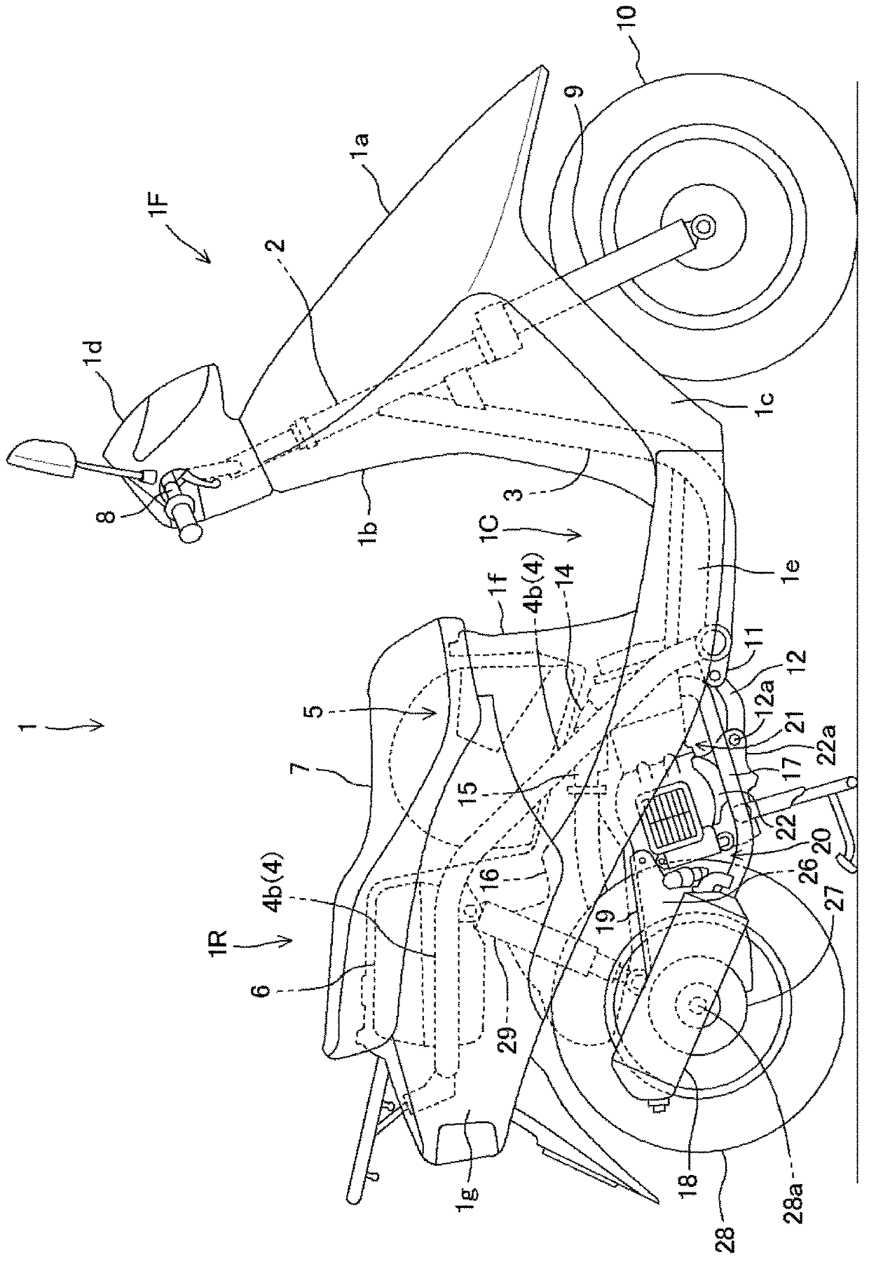
[0105] Below, refer to Figure 1 to Figure 13 , and the first embodiment according to the present invention will be described.

[0106]A scooter-type motorcycle 1 equipped with the unit swing type internal combustion engine according to the present embodiment is, for example, figure 1 shown.

[0107] In the present embodiment, front, rear, left, and right are determined based on the state facing the forward direction of the vehicle.

[0108] The vehicle body front part 1f and the vehicle body rear part 1r are connected via a low floor part 1c, and the frame constituting the skeleton of the vehicle body is roughly composed of a down pipe 3 and a main pipe 4 .

[0109] That is, the downpipe 3 extends downward from the head pipe 2 of the vehicle body front portion 1f, and the downpipe 3 is horizontally bent at the lower end and extends rearward under the floor portion 1c, and connects a pair of left and right main pipes 4 at the rear end. The main pipe 4 is formed with an incl...


PUM


Abstract

The present invention provides a cooling device for an internal combustion engine, capable of blocking gaps formed at a peripheral part of a blade plate to fully block a cooling air inlet when a movable blind window closes the cooling air inlet of a fan housing, so as to facilitate a heating machine during cold start. In the cooling device for the internal combustion engine having the movable blind window (60) capable of opening or closing the cooling air inlet (53) of the fan housing (50), housing side step parts (56u, 56l, 57u, 57l) are formed along an opening rim of the cooling air inlet (53) of the fan housing (50), blind window side step parts (61id, 61od) opposite to the housing side step parts (56u, 56l, 57u, 57l) are formed at the peripheral part of the blade plate (61) of the movable blind window (60), the blind window side step parts (61id, 61od) and the housing side step parts (56u, 56l, 57u, 57l) are abutted and superposed when the cooling air inlet (53) is closed through rotation of the blade plate (61).

Description

technical field [0001] The present invention relates to a cooling device for cooling an internal combustion engine by sending external air taken in by a cooling fan to an internal combustion engine as cooling air, wherein the cooling fan rotates in conjunction with a crankshaft. Background technique [0002] When starting the internal combustion engine, especially in winter when the temperature is low, it is necessary to accelerate warming up to improve fuel efficiency, but at this time, the cooling fan is driven to take in cooling air to cool the internal combustion engine It will hinder the promotion of warm-up. [0003] Therefore, there is known a cooling device that adjusts the intake of cooling air according to the operating conditions of the internal combustion engine (for example, refer to Patent Document 1). [0004] 【Prior technical literature】 [0005] 【Patent Literature】 [0006] [Patent Document 1] Japanese Publication No. 62-185829 [0007] In Patent Documen...

Claims


Application Information

Patent Timeline
Patent Type & Authority Applications(China)
IPC IPC(8): F01P7/02F01P5/06
CPCB60K11/085B60Y2200/126Y02T10/88
Inventor 饭岛智司小林友和
Owner HONDA MOTOR CO LTD
Why Eureka
Try Eureka