Fuel cell system

A fuel cell system and fuel cell technology, applied in the direction of fuel cells, fuel cell additives, transportation fuel cell technology, etc., can solve the problems of FC degradation suppression that have not been studied, so as to suppress the generation of surplus power or insufficient power and prevent deterioration , The effect of reducing the amount of deterioration

Active Publication Date: 2012-11-14
HONDA MOTOR CO LTD
View PDF6 Cites 6 Cited by
  • Summary
  • Abstract
  • Description
  • Claims
  • Application Information

AI Technical Summary

Problems solved by technology

[0004] As mentioned above, US 2010 / 0047630A1 focuses on the viewpoint of rapid warm-up of FC, but does not study the degradation suppression of FC

Method used


Image

  • Fuel cell system
  • Fuel cell system
  • Fuel cell system

Examples


Embodiment Construction

[0046] 1. Description of the overall composition

[0047] [1-1. Overall composition]

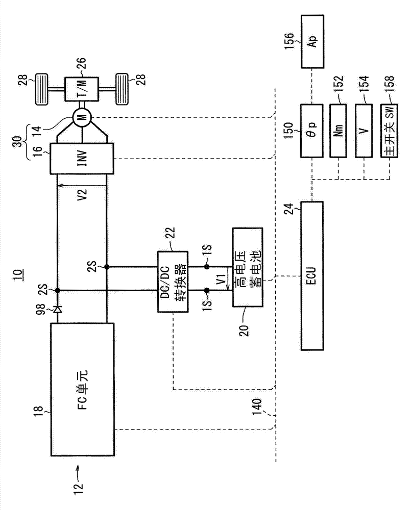
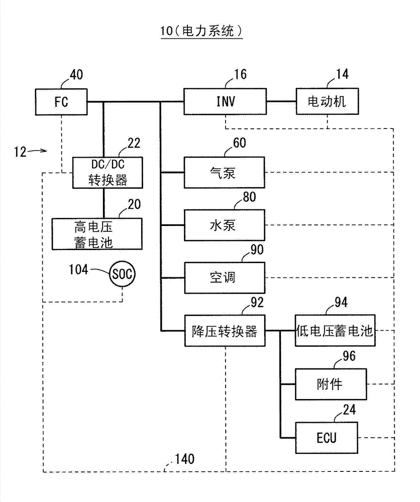
[0048] figure 1 It is a schematic overall configuration diagram of a fuel cell vehicle 10 (hereinafter referred to as "FC vehicle 10") equipped with a fuel cell system 12 (hereinafter referred to as "FC system 12") according to an embodiment of the present invention. figure 2 is a block diagram of the power system of the FC vehicle 10 . Such as figure 1 and figure 2 As shown, the FC vehicle 10 includes, in addition to the FC system 12 , an electric motor 14 and an inverter 16 for traveling.

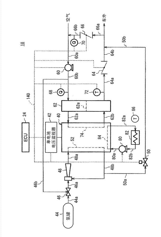
[0049] The FC system 12 has a fuel cell unit 18 (hereinafter referred to as “FC unit 18 ”), a high-voltage battery 20 (hereinafter also referred to as “battery 20 ”) (power storage device), and a DC / DC converter (converter) 22 . The electronic control unit 24 (hereinafter referred to as "ECU24").

[0050] [1-2. Drive system]

[0051]The electric motor 14 generates driving force based on elect...


PUM


Abstract

Provided is a fuel cell system. In a case where a gas supply controller (24) of the FC (Fuel Cell) system (12) determines that the temperature of an FC (40) is a predetermined temperature or less, the gas supply controller fixes the FC voltage to a voltage value within a voltage region where degradation is relatively small, the voltage value being below a voltage range where an oxidation-reduction proceeds. Further, the amount of a gas supplied to the FC (40) is changed in accordance with electric power required by a load (30).

Description

technical field [0001] The present invention relates to a fuel cell system including a fuel cell and a load driven by electric power output from the fuel cell. Background technique [0002] Currently, there is proposed a technique for warming up a fuel cell used in a fuel cell vehicle (US Patent Application Publication No. 2010 / 0047630 (hereinafter referred to as "US 2010 / 0047630A1"). In US 2010 / 0047630A1 In , the output voltage of the fuel cell (FC) is set above the minimum drive voltage of the load power source (abstract). More specifically, the necessity of warming up is judged according to the temperature of the FC ( Figure 4 S2), when it is necessary to warm up (S2: Yes), confirm the motor output request (S3). If there is no request for motor output (S3: No), the first low-efficiency operation is performed to relatively lower the output voltage of the FC (S4, image 3 ). If there is a request for motor output (S3: Yes), the second low-efficiency operation is performe...

Claims


Application Information

Patent Timeline
Patent Type & Authority Applications(China)
IPC IPC(8): H01M8/04B60L11/18
CPCY02T90/34H01M8/04268H02J7/00H01M8/04179H01M8/04753B60L11/1887B60L11/1888Y02E60/50H01M8/04231B60L2210/14H01M8/04559Y02T10/7225B60L58/32B60L58/40Y02T10/70Y02T10/72Y02T90/40
Inventor 数野修一佐伯响
Owner HONDA MOTOR CO LTD
Why Eureka
Try Eureka