Control device for hybrid vehicle power transmitting apparatus

a technology of power transmission apparatus and control device, which is applied in the direction of electric propulsion mounting, transportation and packaging, gearing, etc., can solve the problems of not necessarily having such an effect of control device, and achieve the effect of facilitating a warm-up of the hybrid vehicle power transmission apparatus

Active Publication Date: 2012-01-03
TOYOTA JIDOSHA KK
View PDF13 Cites 7 Cited by
  • Summary
  • Abstract
  • Description
  • Claims
  • Application Information

AI Technical Summary

Benefits of technology

[0004]The present invention has been completed with such a view in mind, and has an object to provide a control device for a hybrid vehicle power transmitting apparatus for use in a hybrid vehicle, having an internal combustion engine and an electric motor, which control device facilitates a warm-up of the hybrid vehicle power transmitting apparatus.

Problems solved by technology

However, the control device, disclosed in Patent Publication 1, does not necessarily have such an effect of facilitating the warm-up of the hybrid vehicle power transmitting apparatus.

Method used


Image

  • Control device for hybrid vehicle power transmitting apparatus
  • Control device for hybrid vehicle power transmitting apparatus
  • Control device for hybrid vehicle power transmitting apparatus

Examples


first embodiment

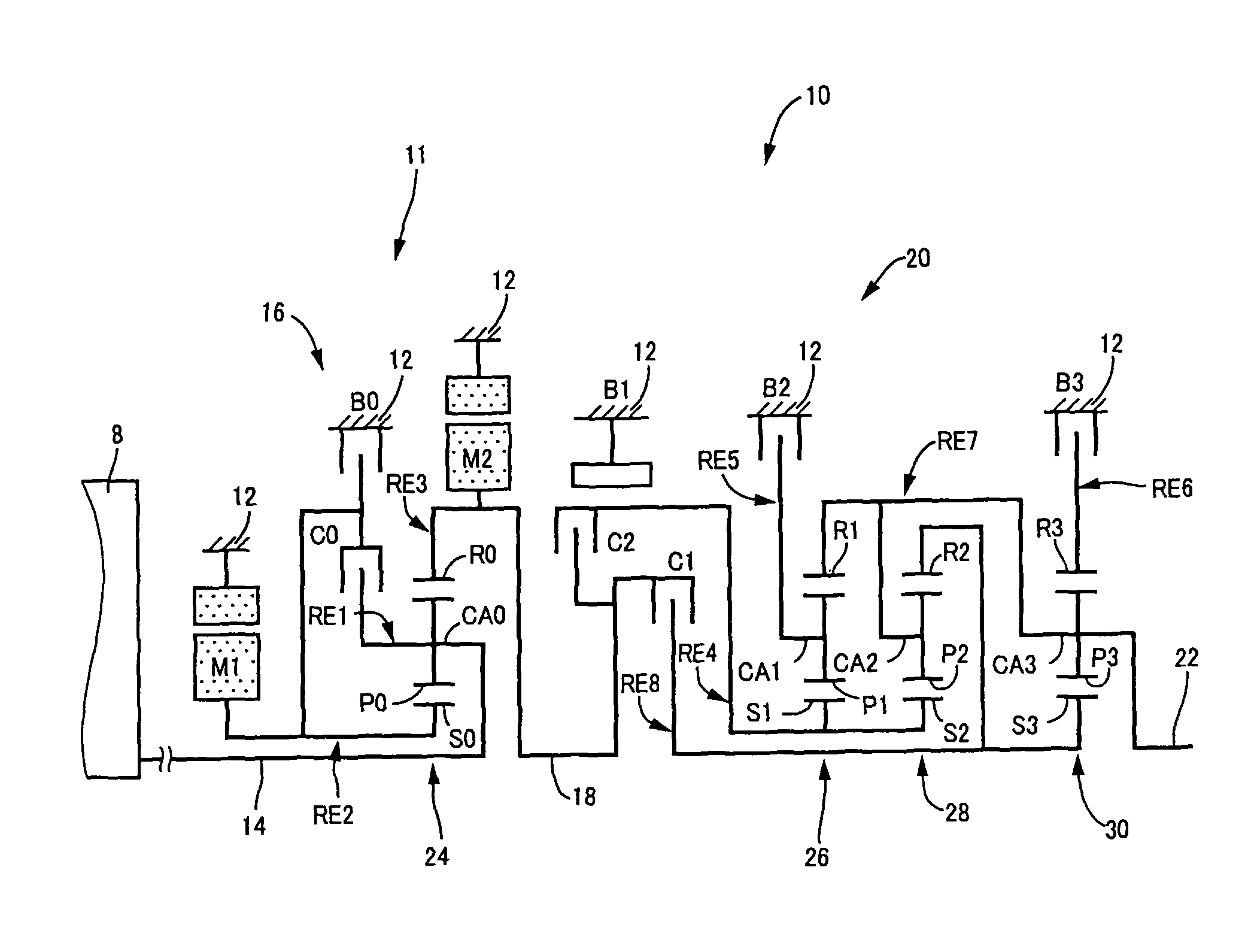
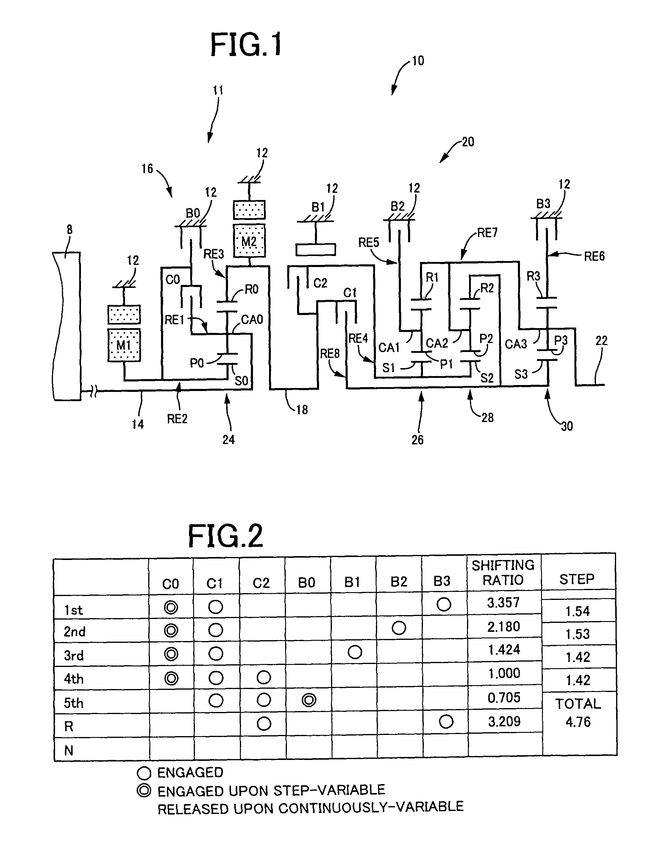
[0048]FIG. 1 is a skeleton view illustrating a shifting mechanism 10, forming part of a power transmitting apparatus for a hybrid vehicle, to which a control device of one embodiment according to the present invention is applied. As shown in FIG. 1, the shifting mechanism 10 includes an input shaft 14 serving as an input rotary member, a differential portion 11 directly connected to the input shaft 14 or indirectly connected thereto through a pulsation absorbing damper (vibration damping device) not shown, an automatic shifting portion 20 connected via a power transmitting member (transmission shaft) 18 in series through a power transmitting path between the differential mechanism 11 and drive wheels 38 (see FIG. 6) to serve as a step-variable type transmission, and an output shaft 22 connected to the automatic shifting portion 20 as an output rotary member. All of them are disposed in a transmission casing 12 (hereinafter briefly referred to as a “casing 12”) serving as a non-rotar...

second embodiment

[0168]With a second embodiment, the shifting mechanism 10 of the first embodiment is replaced by a shifting mechanism 210 shown in FIG. 12. FIG. 12 is a skeleton view, illustrating the shifting mechanism 210 forming part of a hybrid vehicle power transmitting apparatus to which the present invention is applied, which shows a structure basically corresponding to the first embodiment shown in FIG. 1 with the exception that the switching clutch C0 and the switching brake B0 are omitted.

[0169]As shown in FIG. 12, the shifting mechanism 210 includes the input shaft 14 serving as the input rotary member coaxially disposed in the transmission case (hereinafter referred to as “case 12”) mounted on the vehicle body to act as the non-rotary member, a differential portion 211 directly connected to the input shaft 14 or indirectly connected thereto via a pulsation absorbing damper (vibration damping device) (not shown) to act as a continuously variable shifting portion, the automatic shifting p...


PUM


Abstract

This invention relates to a control device for a hybrid vehicle power transmitting apparatus. A heat generation control is executed to increase a heat generation amount of an electric motor M1 when a differential portion 11 is placed in a non-differential state and a temperature of a shifting mechanism 10 is less than a given transmitting apparatus temperature determining value TEMP11. This allows the first electric motor M1 to develop a heat with which the temperature of a shifting mechanism 10 is promptly raised, thereby promptly completing a warm-up of the shifting mechanism 10 to achieve improved fuel consumption.

Description

TECHNICAL FIELD[0001]The present invention relates to a control device for a hybrid vehicle power transmitting apparatus for use in a hybrid vehicle having an internal combustion engine and an electric motor. More particularly, it relates to a technology of facilitating a warm-up of the hybrid vehicle power transmitting apparatus.BACKGROUND ART[0002]There has been known a hybrid vehicle power transmitting apparatus including a differential mechanism for distributing an output of an engine, such as an internal combustion engine to a power transmitting path between a first electric motor and drive wheels, a differential-action limiting device that limits a differential action of the differential mechanism or canceling such a differential action, and a second electric motor connected to a power transmitting apparatus extending from the differential mechanism to the drive wheels. For instance, Patent Publication 1 (Japanese Patent Application Publication No. 2006-46386) discloses in FIG...

Claims


Application Information

Patent Timeline
Patent Type & Authority Patents(United States)
IPC IPC(8): B60W20/00B60K6/445B60K6/543B60K6/547B60L50/16B60W10/08B60W10/10
CPCB60K6/365B60K6/445B60K6/547B60W10/08B60W30/194F16H57/0413B60K6/40Y10T477/653B60L2240/425B60L2240/485B60W20/00B60W2510/087B60W2510/107F16H2037/0873Y02T10/642Y02T10/6239Y10T477/26Y10T477/23Y02T10/62Y02T10/64
Inventor IMAMURA, TATSUYAIWASE, YUJITABATA, ATSUSHI
Owner TOYOTA JIDOSHA KK
Why Eureka
Try Eureka