
Optical Fiber with Sequential Varying Core Profile Zones

a technology of optical fiber and core profile, applied in the field of system and method of fabrication, can solve the problems of increasing the cost and potential waste of optical fiber, simply losing energy, and generally cost prohibitive products of specialty optical fibers for research and developmen

Pending Publication Date: 2021-09-30
ORTRONICS INC
View PDF3 Cites 0 Cited by
  • Summary
  • Abstract
  • Description
  • Claims
  • Application Information

AI Technical Summary

Benefits of technology

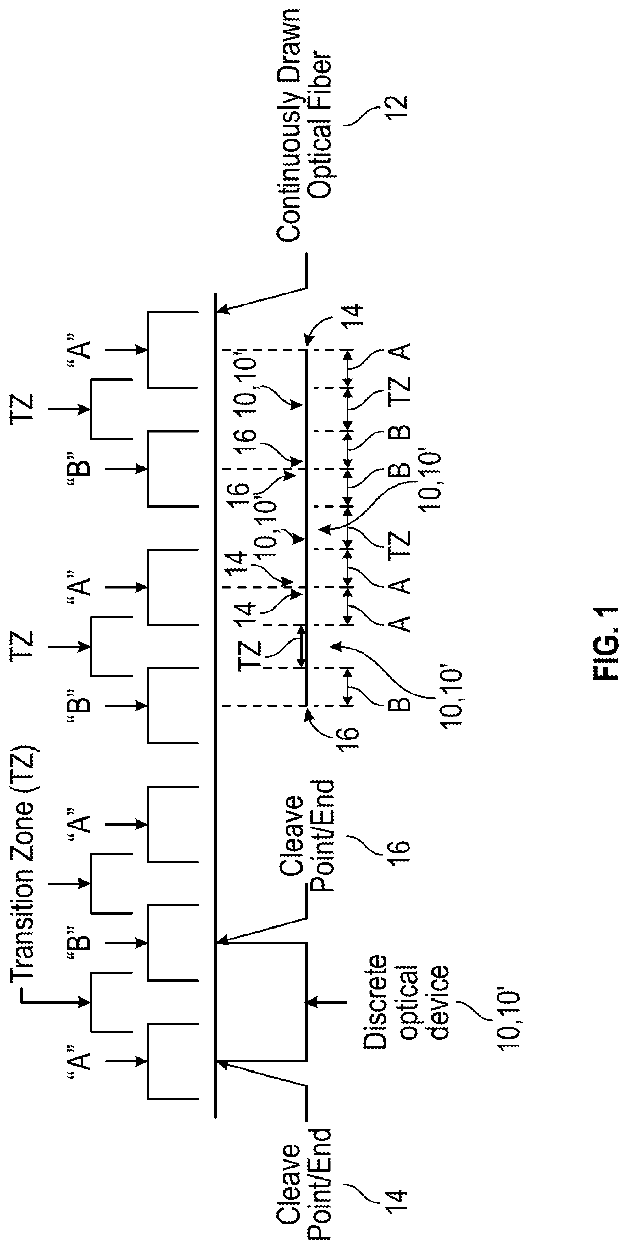
The present patent offers better optical devices and methods for making them. It introduces a fabrication process for discrete passive optical devices that uses a cyclic core variance. Additionally, the patent presents improved systems and methods for making optical fibers, which involve adjusting the drawing speed during fabrication to create continuous optical fibers with different core index profile diameters. This results in different fiber sizes that can be made in a single run, reducing production costs and minimizing waste for the end user.

Problems solved by technology

This lead still collects its share of energy in the merging direction, but this energy is simply lost.
This can be problematic if the end user only needs tens or hundreds of meters worth of optical fiber.
Due to the standard length of conventional optical fibers, such end users may be forced to purchase an entire run of fiber, resulting in increased costs and potential waste of the optical fiber.
Product of specialty optical fibers for research and development is generally cost prohibitive due to limitations on minimum length for production, and the production time required to form the specialty fibers.

Method used


Image

  • Optical Fiber with Sequential Varying Core Profile Zones
  • Optical Fiber with Sequential Varying Core Profile Zones
  • Optical Fiber with Sequential Varying Core Profile Zones

Examples


Embodiment Construction

[0055]The exemplary embodiments disclosed herein are illustrative of advantageous optical devices (e.g., discrete passive optical devices), and systems of the present disclosure and fabrication methods / techniques thereof. It should be understood, however, that the disclosed embodiments are merely exemplary of the present disclosure, which may be embodied in various forms. Therefore, details disclosed herein with reference to exemplary optical devices / fabrication methods and associated processes / techniques of assembly and use are not to be interpreted as limiting, but merely as the basis for teaching one skilled in the art how to make and use the advantageous optical devices / systems and / or alternative optical devices / systems of the present disclosure.

[0056]The present disclosure provides improved optical devices (e.g., discrete passive optical devices), and improved systems and methods for fabricating such optical devices. More particularly, the present disclosure provides advantageo...


PUM

PropertyMeasurementUnit
Lengthaaaaaaaaaa
Diameteraaaaaaaaaa

Abstract

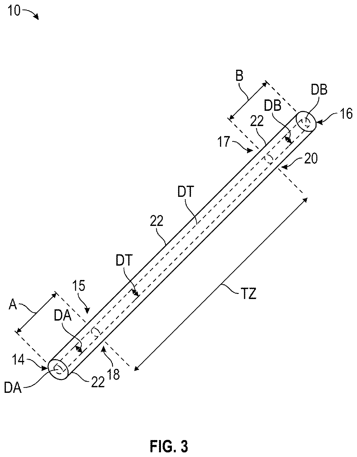
The present disclosure provides an optical fiber and a method of fabricating an optical fiber. The method includes providing an optical fiber, the optical fiber defining a length having a proximal end and a distal end. The optical fiber includes a first core profile zone defining a first core diameter, and a second core profile zone defining a second core diameter different from the first core diameter. The optical fiber includes a first transition zone connecting the first core profile zone to the second core profile zone. The first core profile zone, the second core profile zone, and the first transition zone are formed as a single, continuous fiber.

Description

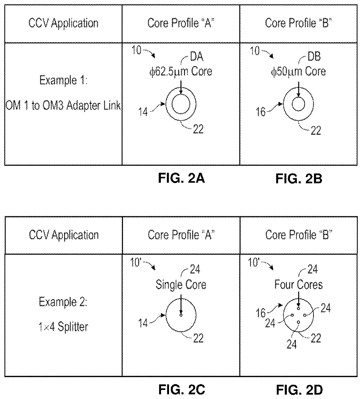
CROSS-REFERENCE TO RELATED APPLICATIONS[0001]This application is a continuation-in-part application of, and claims priority to, U.S. Non-Provisional patent application Ser. No. 16 / 390,582, which was filed on Apr. 22, 2019, which claims the benefit of U.S. Provisional Patent Application entitled “CYCLIC CORE VARIANCE SYSTEM,” which was filed on Apr. 23, 2018, and assigned Ser. No. 62 / 661,466, the entire contents of the foregoing patent applications hereby expressly incorporated by reference in their entirety.FIELD OF THE DISCLOSURE[0002]The present disclosure relates to systems and methods of fabrication, and more particularly, to fabrication of an optical fiber with sequential varying core profile zones. The present disclosure also relates to systems and methods of fabrication of optical fibers with a sequential varying core structures, such as but not limited to, index profile, locations, number of cores, core shapes, or the like. The present disclosure also relates to optical devi...

Claims


Application Information

Patent Timeline
IPC IPC(8): G02B6/02C03B37/012B33Y80/00C03B37/025C03B37/027B29D11/00
CPCG02B6/02042C03B37/012B29D11/00721C03B37/0253C03B37/027B33Y80/00G02B6/262G02B6/2804C03B37/018C03B2203/18
Inventor HUANG, LEISMITH, DANIEL M.
Owner ORTRONICS INC
Learn More