
Machine, system, and method for automated milling exit cut operation

Active Publication Date: 2021-10-07
CATERPILLAR PAVING PROD INC
View PDF0 Cites 0 Cited by
  • Summary
  • Abstract
  • Description
  • Claims
  • Application Information

AI Technical Summary

Benefits of technology

The present patent describes a method, system, and milling machine for automated exit cut operations. The method involves raising the rotor of a milling machine from a state where it contacts the ground surface material and determining when the bottom portion of the rotor reaches the top surface of the ground surface material. The rotor is then controlled to rise at a rate that increases as the rotor reaches the top surface, resulting in a maximum rate of rise. This method can improve the efficiency and accuracy of the milling process. The system includes a controller that controls the automated exit cut operation based on settings and signals from sensors, allowing for smoother and more precise operation. Overall, this patent aims to enhance the performance and efficiency of milling machines for improved ground surface processing.

Problems solved by technology

Conventionally a milling machine, such as a rotary mixer or a cold planer, may leave an undesirable divot or pile of material at the end of a cutting pass.
However, the '755 patent is not understood to describe changing the speed at which the milling device is raised based on the position of the milling device relative to the worked ground surface.

Method used


Image

  • Machine, system, and method for automated milling exit cut operation
  • Machine, system, and method for automated milling exit cut operation
  • Machine, system, and method for automated milling exit cut operation

Examples


Embodiment Construction

[0019]The present disclosure relates to automated operations for a milling machine, and more particularly to an automated exit cut operation of the milling machine.

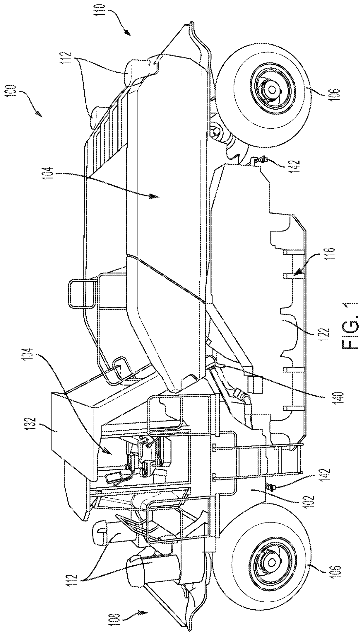
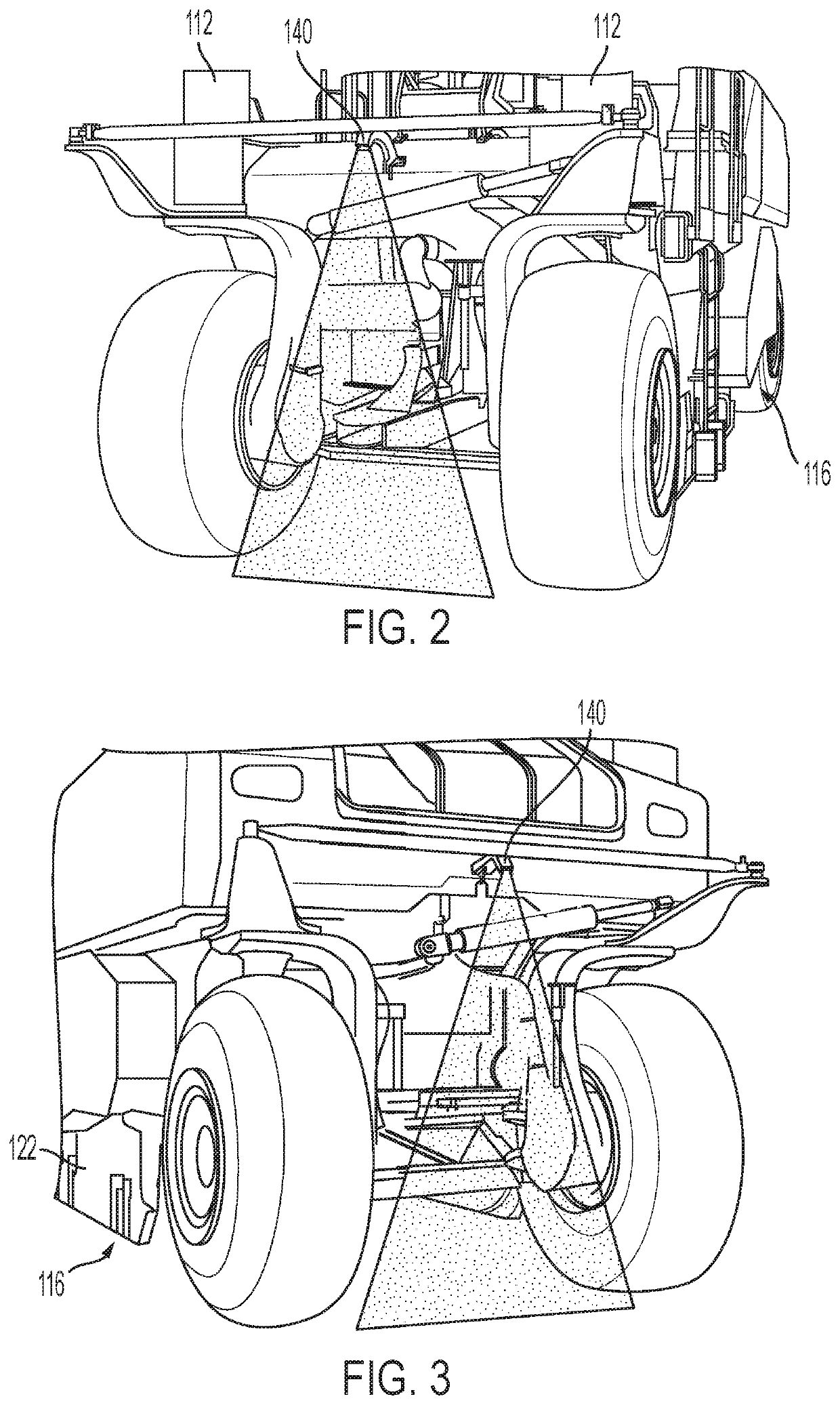
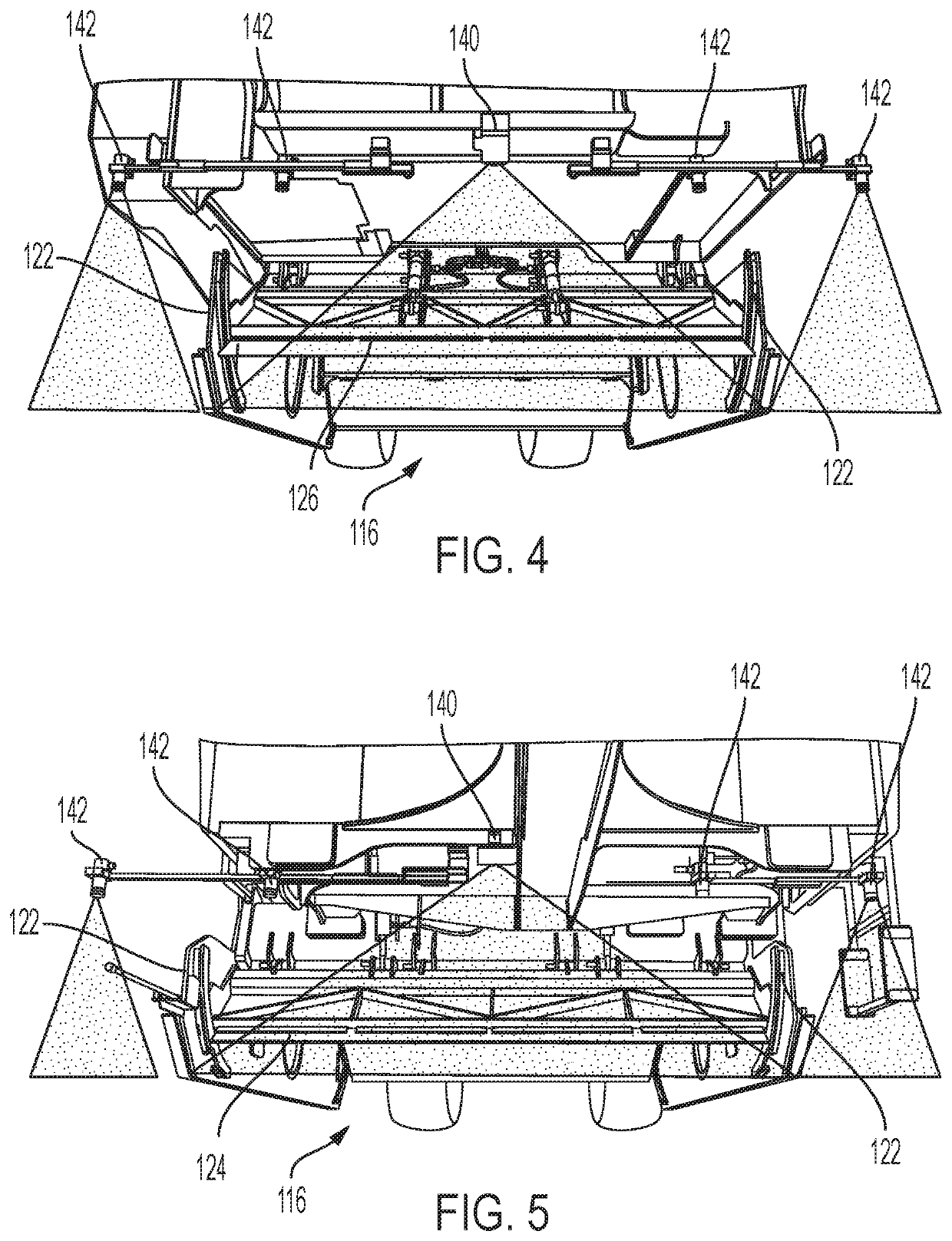
[0020]Referring now to the drawings, FIG. 1 is a side perspective view of a milling machine 100 according to one or more embodiments of the disclosed subject matter. The milling machine 100 of FIG. 1 is a rotary mixer. Generally, rotary mixers can be used to pulverize a ground surface, such as roadways based on asphalt, and mix a resulting pulverized layer with an underlying base, to stabilize the ground surface. Rotary mixers may also be used as a soil stabilizer to cut, mix, pulverize, and stabilize a soil surface, for instance, to attain a strengthened soil base. Optionally, rotary mixers may add asphalt emulsions or other binding agents during pulverization to create a reclaimed surface. Though the milling machine 100 is shown as a rotary mixer, other machines for road reclamation, soil stabilization, surface pulveriz...


PUM


Abstract

A milling machine, system, and method for implementing an exit cut operation raises a rotor from a state where the rotor contacts ground surface material responsive to a control input at an operator control interface of the milling machine. The rate at which the rotor is raised can increase as the rotor is raised. When the rotor is determined to have reached a top surface of the ground surface material the rotor can be raised at a maximum rate.

Description

TECHNICAL FIELD[0001]The present disclosure relates to automated operations for a milling machine, and more particularly to an automated exit cut operation for the milling machine.BACKGROUND[0002]Conventionally a milling machine, such as a rotary mixer or a cold planer, may leave an undesirable divot or pile of material at the end of a cutting pass.[0003]U.S. Pat. No. 8,485,755 (“the '755 patent”) describes that a controller for terminating the milling process controls the milling depth of a milling device along a specified trajectory in conjunction with simultaneous forward and reverse travel. According to the '755 patent, such control enables the milling device to be raised into an upper position disengaged from the ground without a depression resulting from raising the milling device remaining in the worked ground surface. However, the '755 patent is not understood to describe changing the speed at which the milling device is raised based on the position of the milling device rel...

Claims


Application Information

Patent Timeline
IPC IPC(8): E01C23/06E01C23/088
CPCE01C23/065E01C23/088
Inventor DOY, NATHANIELMUIR, JASON W.HOGAN, LEE M.
Owner CATERPILLAR PAVING PROD INC
Learn More