Flow control techniques for delaying or accelerating laminar-turbulent boundary-layer transition for high-speed flight vehicles

Pending Publication Date: 2021-10-14
THE ARIZONA BOARD OF REGENTS ON BEHALF OF THE UNIV OF ARIZONA
View PDF1 Cites 7 Cited by
  • Summary
  • Abstract
  • Description
  • Claims
  • Application Information

AI Technical Summary

Benefits of technology

[0011]Embodiments are directed to novel flow control techniques for modifying the “natural” (uncontrolled) laminar to turbulent transition process of the flow in the boundary layer of vehicles, projectiles or missiles (“vehicles”) at supersonic/hypersonic speeds (“high-speed”). The boundary layer is a very thin layer of fluid that develops near the skin of vehicles, projectiles or missiles at any flow speed. The fluidic state of the boundary layer, laminar, transitional or turbulent, determines the degree of skin friction and heating of high-speed vehicles. The drag caused by skin friction contributes a large portion to the total drag of a high-speed vehicle. Higher drag reduces the range and/or maximum payload of the vehicle. High wall-heating requi

Problems solved by technology

The drag caused by skin friction contributes a large portion to the total drag of a high-speed vehicle.
Higher drag reduces the range and/or maximum payload of the vehicle.
In addition, for hypersonic flows, the nonlinear interactions in the transition regime can lead to the development of streamwise streaks of locally very high skin friction and h

Method used


Image

  • Flow control techniques for delaying or accelerating laminar-turbulent boundary-layer transition for high-speed flight vehicles
  • Flow control techniques for delaying or accelerating laminar-turbulent boundary-layer transition for high-speed flight vehicles
  • Flow control techniques for delaying or accelerating laminar-turbulent boundary-layer transition for high-speed flight vehicles

Examples


Example

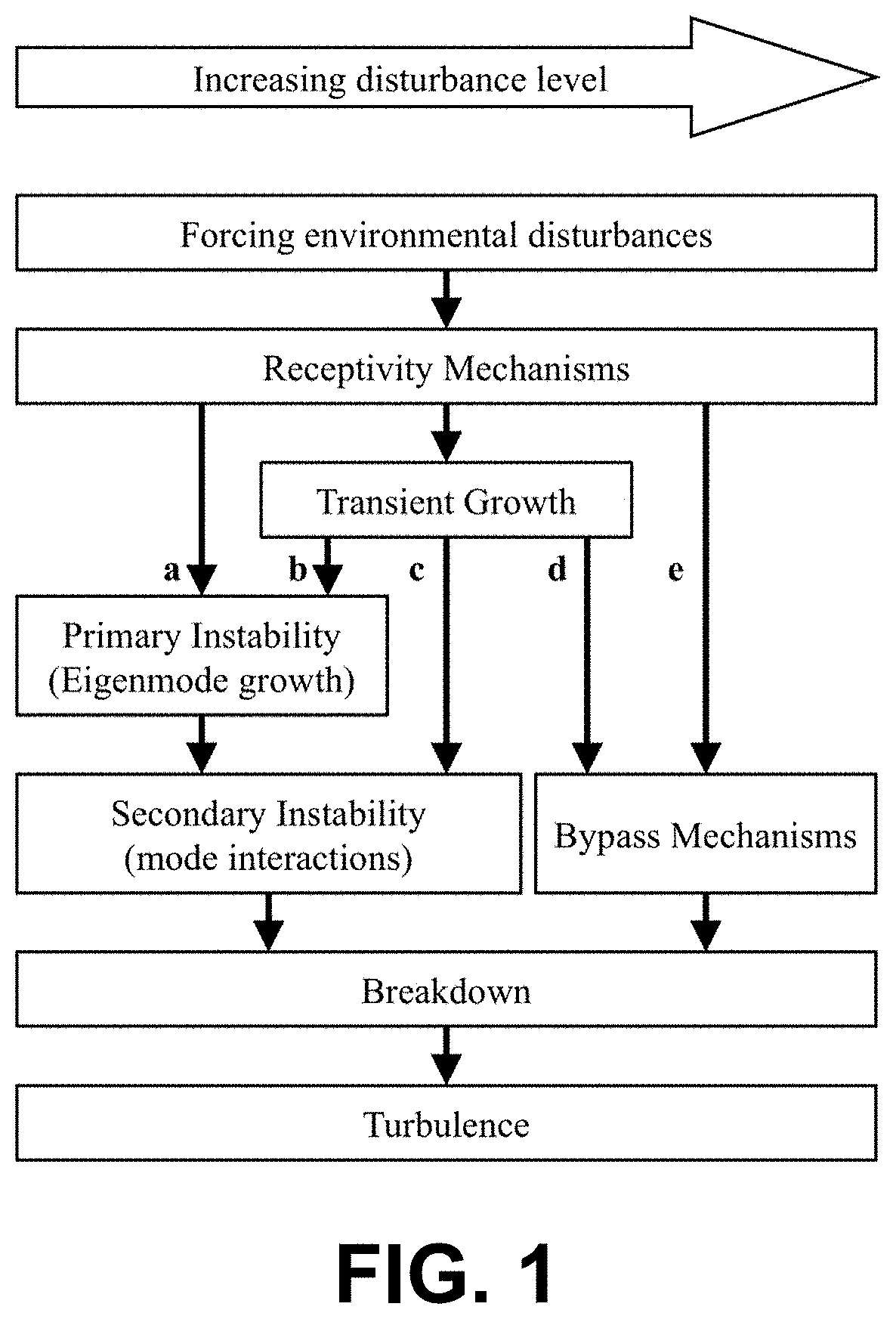
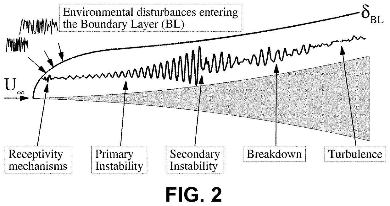
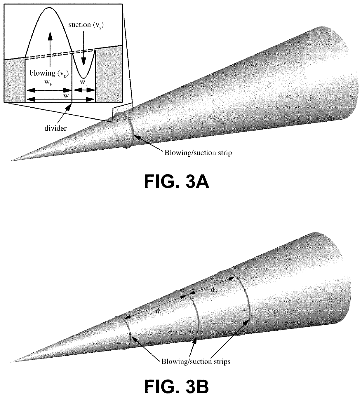
[0041]It is to be understood that the figures and descriptions of the present invention may have been simplified to illustrate elements that are relevant for a clear understanding of the present invention, while eliminating, for purposes of clarity, other elements found in a typical high-speed vehicle or typical method of using / operating a high-speed vehicle. Those of ordinary skill in the art will recognize that other elements may be desirable and / or required in order to implement the present invention. However, because such elements are well known in the art, and because they do not facilitate a better understanding of the present invention, a discussion of such elements is not provided herein. It is also to be understood that the drawings included herewith only provide diagrammatic representations of the presently preferred structures of the present invention and that structures falling within the scope of the present invention may include structures different than those shown in...


PUM


Abstract

A system and method for controlling boundary layer transition for a high-speed vehicle are disclosed. The method includes determining a location of onset of boundary-layer transition that naturally develops during high-speed flight of the high-speed vehicle, and providing a pair of flow control strips at a surface/wall/skin of the high-speed vehicle such that the boundary-layer transition is delayed or prevented during high-speed flight of the high-speed vehicle. The delayed or prevented locations of the transition result in a change in the high-speed boundary layer during the high-speed flight of the high-speed vehicle. The change in the high-speed boundary layer transition affects skin friction drag, aero-thermodynamic heating, and pressure fluctuations in the boundary layer of the high-speed vehicle.

Description

CROSS REFERENCE TO RELATED APPLICATION(S)[0001]This application claims priority to U.S. provisional patent application No. 62 / 953,367, filed on Dec. 24, 2019, which is hereby incorporated herein by reference in its entirety.GOVERNMENT SPONSORSHIP[0002]This invention was made with government support under Grant No. FA9550-15-1-0265 awarded by the Air Force Office of Scientific Research. The government has certain rights in the invention.FIELD OF THE INVENTION[0003]Embodiments are in the field of high-speed boundary layer transition. More particularly, embodiments disclosed herein relate to systems and methods for controlling high-speed boundary layer transition via various flow control techniques which, inter alia, foster enhanced aerodynamic performance, reduced aero-thermodynamic heating, and improved vehicle guidance and control characteristics of high-speed flight vehicles.BACKGROUND OF THE INVENTION[0004]Laminar-turbulent transition in hypersonic boundary layers is a major unres...

Claims


Application Information

Patent Timeline
IPC IPC(8): B64C21/02B64C23/00B64C30/00
CPCB64C21/025B64C30/00B64C23/005B64C21/04B64C21/06Y02T50/10
Inventor FASEL, HERMANN F.HADER, CHRISTOPH
Owner THE ARIZONA BOARD OF REGENTS ON BEHALF OF THE UNIV OF ARIZONA
Why Eureka
Try Eureka