
Archery bow sight

Inactive Publication Date: 2021-10-21
H I T OUTDOORS LLC
View PDF15 Cites 1 Cited by
  • Summary
  • Abstract
  • Description
  • Claims
  • Application Information

AI Technical Summary

Benefits of technology

The patent describes a bow sight that allows for easy and accurate calibration for different shooting ranges. The sight is connected to the arm of the user through a mounting bracket that can be adjusted to different positions relative to the riser. The sight housing can also be adjusted in relation to the mounting bracket for added precision. Additionally, the sight is designed to allow for both individual and collective calibration of the pins, eliminating the need for a separate secondary vertical adjuster. This simplifies the construction and assembly process of the sight.

Problems solved by technology

In so doing, however, the archer with a conventional sight might only be able to move their sight so much with a conventional vertical adjustment mechanism.
Due to the movement of the individual pins, those pins also might not be moved properly to replicate the previous spacing, in which case the pins will need to be tediously recalibrated.

Method used


Image

  • Archery bow sight
  • Archery bow sight
  • Archery bow sight

Examples


Embodiment Construction

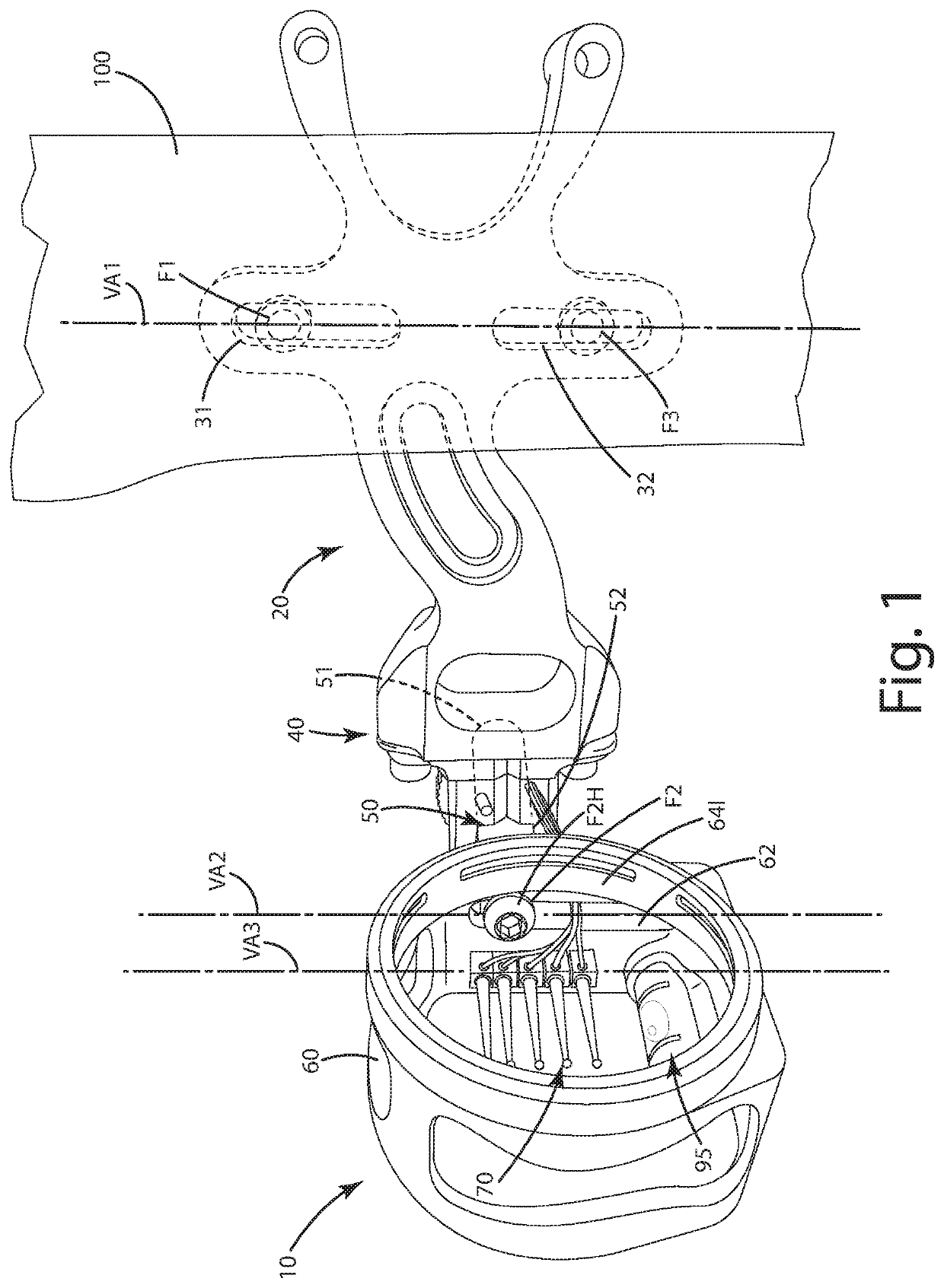
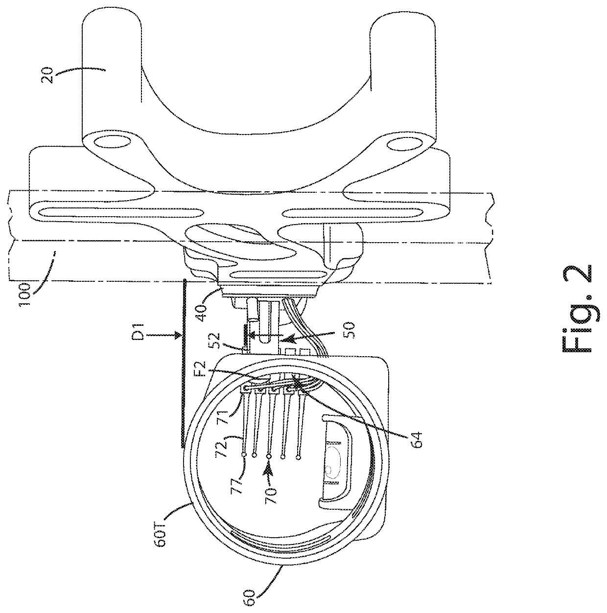
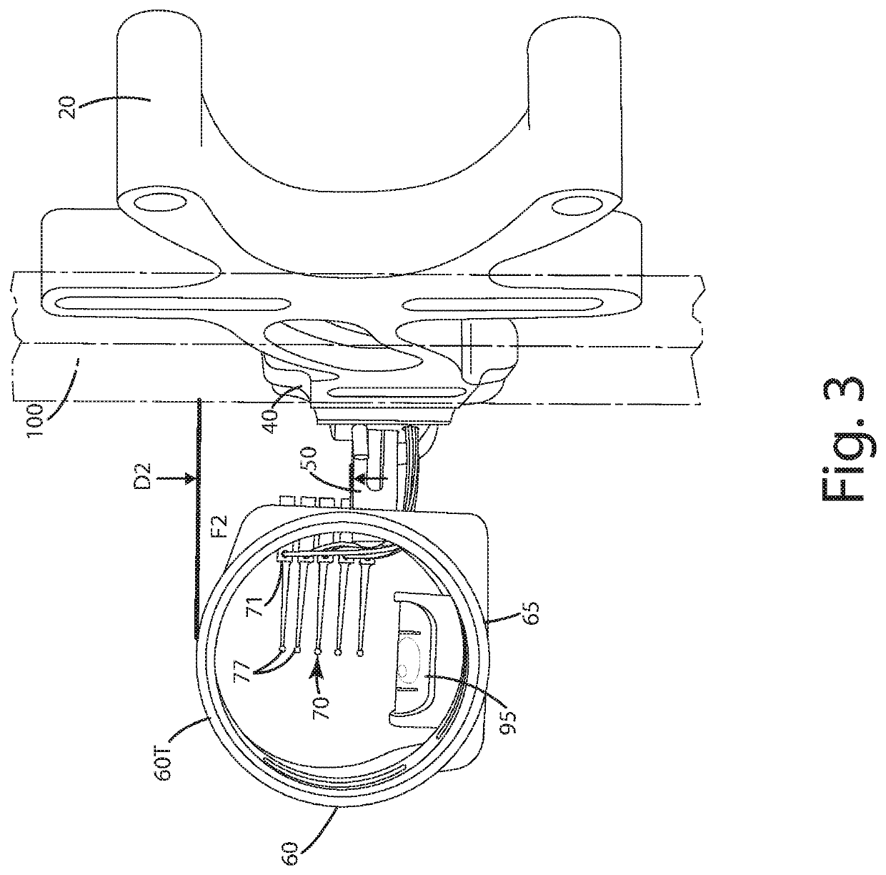
[0024]A bow sight constructed in accordance with an embodiment of the invention is illustrated in FIGS. 1-9 and generally designated 10. The bow sight 10 can include a mounting bracket 20, a windage adjuster 40 having an arm 50 that joins with a sight housing 60 within which one or more pins 70 are located. For purposes of this disclosure, the bow sight is described in connection with its use on an archery bow, however, the construction is well suited for use with any projectile shooting device. The bow sight 10 can be joined with an archery bow riser or other component 100 via the mounting bracket 20. The archery bow riser 100 can define first and second holes 101, 102 which can be threaded to receive a corresponding fastener.

[0025]In particular, as shown in FIGS. 1 and 2, the fasteners F1 and F2 can be disposed within or through the substantially vertical elongated first slot 31 and third slot 32 defined by the mounting bracket. The first slot 31 can be disposed directly above the...


PUM


Abstract

A bow sight is provided including a mounting bracket including a proximal end and a distal end, a sight housing and a sight pin mounted in the housing. The proximal end can define substantially vertical slots, one above the other, to provide a first vertical adjustment of the archery bow sight. The sight housing can define another substantially vertical slot. The mounting bracket can be joined with an arm that is movable relative to the substantially vertical housing slot so that the sight housing and sight pin can be vertically adjusted up and down, moving simultaneously with one another, relative to the mounting bracket to provide a second vertical adjustment of the archery bow sight. The arm can extend from a windage adjuster mounted to the mounting bracket.

Description

BACKGROUND OF THE INVENTION[0001]The present invention relates to archery sights, and in particular, to archery sights having a wide range of vertical movement to accommodate different shooting distances.[0002]Most conventional archery bows are outfitted with sights that are designed to align the trajectory of an arrow shot from the bow with a target or game. These bow sights include sight pins to be aligned with the target for accurate shooting. Archers or bow hunters often desire to shoot targets or game at different distances. Accordingly, most bow sights include multiple sight pins having sight indicia aligned along a vertical axis, one over the other. Each sight indicia is calibrated for a target at a different range. Depending on the target range, the archer must select the corresponding sight pin and align its sight indicia with the target. If the archer's range estimation, pin selection and indicia alignment are correct when the archer shoots the arrow, the arrow will hit th...

Claims


Application Information

Patent Timeline
IPC IPC(8): F41G1/467F41G3/08
CPCF41G1/467F41G3/08F41G1/44
Inventor JONES, BRIAN K.
Owner H I T OUTDOORS LLC
Learn More