Unlock instant, AI-driven research and patent intelligence for your innovation.

Pointer device

a pointer device and pointer device technology, applied in the direction of instruments, power supplies for data processing, computing, etc., can solve the problems of high power consumption, inability to operate synchronously between the pointer device and the electromagnetic coordinate positioning apparatus, and complex decoding instructions of non-fixed durations

Active Publication Date: 2021-11-04
SHENZHEN PU YING INNOVATION TECH CORP LTD
View PDF0 Cites 0 Cited by
  • Summary
  • Abstract
  • Description
  • Claims
  • Application Information

AI Technical Summary

Benefits of technology

The patent is for a pointer device that uses an induction coil, a clock generating circuit, and a control circuit. The induction coil converts magnetic energy into electrical potential energy and stores it for use in a power storage period. The control circuit decodes an instruction signal from the electromagnetic coordinate positioning apparatus and generates a clock signal. The clock signal is used to determine which instruction signal the control circuit should respond to. When the control circuit receives an instruction signal, it triggers the induction coil to send a data signal to the electromagnetic coordinate positioning apparatus in the data transmission period. The data signal contains a fixed quantity of bits that are sent at different timings to respond to the instruction signal. This invention allows for precise positioning and data transmission using a pointer device.

Problems solved by technology

The process of decoding instructions of non-fixed durations is rather complex.
As a result, the pointer device and the electromagnetic coordinate positioning apparatus cannot operate synchronously.
In addition, the pointer device is difficult to implement, its circuit needs to be implemented using complex circuit elements, and high power consumption is required.
When we want to analyze the pressure data at higher pressure levels, the speed of calculating and digitizing the pressure data by using the charging and discharging technique in combination with a fixed-frequency clock is low, and it takes a long time for the pointer device to report the pressure data, leading to a low report rate.

Method used


Image

  • Pointer device
  • Pointer device
  • Pointer device

Examples


Embodiment Construction

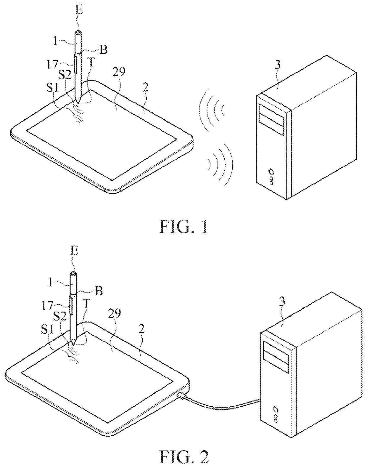
[0014]FIG. 1 and FIG. 2 are respectively diagrams of an embodiment of a pointer device 1 and an embodiment of an electromagnetic coordinate positioning apparatus 2 applicable to the pointer device 1. Referring to FIG. 1 and FIG. 2, the electromagnetic coordinate positioning apparatus 2 includes a working area 29. The pointer device 1 may or may not contact with the working area 29 of the electromagnetic coordinate positioning apparatus 2. When the pointer device 1 is close to the working area 29, the electromagnetic coordinate positioning apparatus 2 may sense an induction signal of the pointer device 1 and receive a signal sent by the pointer device 1. When the pointer device 1 is pressed on the working area of the electromagnetic coordinate positioning apparatus 2, the electromagnetic coordinate positioning apparatus 2 may further receive a pressure signal from the pointer device 1. In addition, as shown in FIG. 1 and FIG. 2, the electromagnetic coordinate positioning apparatus 2 ...


PUM


Abstract

A pointer device is provided. The pointer device includes an induction coil, a clock generating circuit, and a control circuit. The induction coil converts magnetic energy into electrical potential energy and stores the electrical potential energy in a power storage period, and receives an instruction signal from the electromagnetic coordinate positioning apparatus in an instruction receiving period. The control circuit decodes the instruction signal in the instruction receiving period according to the clock signal after the power storage period. When determining that the instruction signal is one of a plurality of predefined instructions, the control circuit triggers, in a data transmission period, the induction coil to send a data signal corresponding to the instruction signal to the electromagnetic coordinate positioning apparatus according to the clock signal after the instruction receiving period. The instruction signal and the data signal each include a fixed quantity of bits.

Description

CROSS-REFERENCE TO RELATED APPLICATION[0001]This non-provisional application claims priority under 35 U.S.C. § 119(a) to Patent Application No. 202010366081.2 filed in China, P.R.C. on Apr. 30, 2020, the entire contents of which are hereby incorporated by reference.BACKGROUNDTechnical Field[0002]An embodiment of the present invention relates to a pointer device, and in particular, to a pointer device for an electromagnetic coordinate positioning apparatus.Related Art[0003]For conventional pointer devices, an electromagnetic coordinate positioning apparatus sends instructions of non-fixed durations to a pointer device. The process of decoding instructions of non-fixed durations is rather complex. The pointer device reports data of non-fixed durations to the electromagnetic coordinate positioning apparatus. In other words, the time for which the pointer device needs to operate varies with different instructions sent by the electromagnetic coordinate positioning apparatus. As a result,...

Claims


Application Information

Patent Timeline
Patent Type & Authority Applications(United States)
IPC IPC(8): G06F3/0354G06F3/041
CPCG06F3/03545G06F3/04146G06F3/04162G06F3/03543G06F3/0354G06F3/046G06F1/26
Inventor HSU, CHUNG-WEN
Owner SHENZHEN PU YING INNOVATION TECH CORP LTD
Features
  • R&D
  • Intellectual Property
  • Life Sciences
  • Materials
  • Tech Scout
  • Unparalleled Data Quality
  • Higher Quality Content
  • 60% Fewer Hallucinations
Learn More