Power supply device and vehicle equipped with same

Pending Publication Date: 2021-11-11
SANYO ELECTRIC CO LTD
View PDF0 Cites 1 Cited by
  • Summary
  • Abstract
  • Description
  • Claims
  • Application Information

AI Technical Summary

Benefits of technology

The patent text describes a battery stack design that improves durability and stability over a long period of time. The design involves distributing stress over wide areas, instead of concentrating it on specific parts of the battery stack. This reduces the risk of failure and ensures a steady holding force.

Problems solved by technology

As a result, it is possible that screws fixing the bind bars are broken.

Method used


Image

  • Power supply device and vehicle equipped with same
  • Power supply device and vehicle equipped with same
  • Power supply device and vehicle equipped with same

Examples


first exemplary embodiment

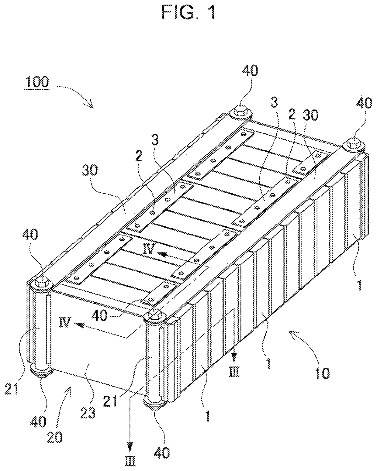
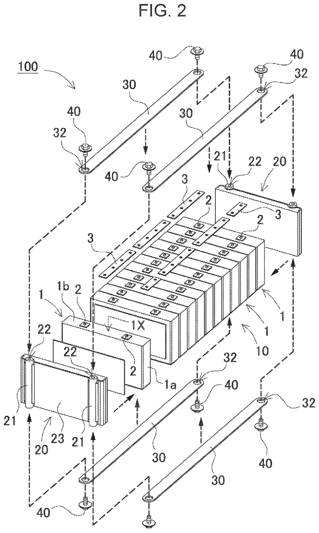
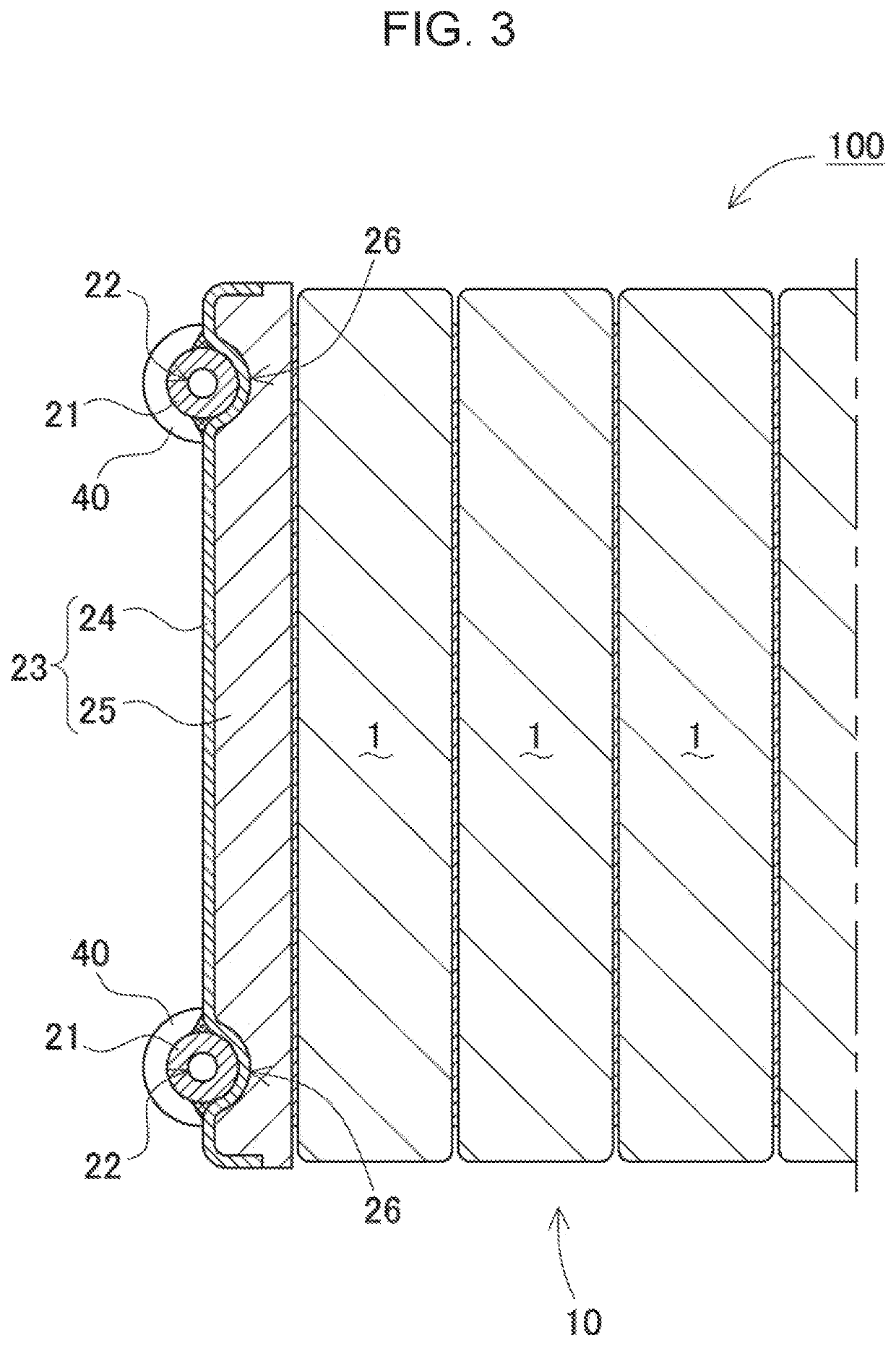
[0035]FIG. 1 is a perspective view of power supply device 100 according to a first exemplary embodiment of the present invention, FIG. 2 is an exploded perspective view of power supply device 100, FIG. 3 is a horizontal cross-sectional view taken along line III-III in FIG. 1, and FIG. 4 is a vertical cross-sectional view taken along line IV-IV in FIG. 1. power supply device 100 illustrated in FIGS. 1 to 4 includes a plurality of secondary battery cells 1 having positive and negative electrode terminals 2 and bus bars 3 that are connected to electrode terminals 2 of the plurality of secondary battery cells 1 and connect the plurality of secondary battery cells 1 in parallel and in series. The plurality of secondary battery cells 1 are connected in parallel or in series via bus bars 3. Secondary battery cell 1 is a rechargeable secondary battery. In power supply device 100, the plurality of secondary battery cells 1 are connected in parallel to form a parallel battery group, and a plu...

second exemplary embodiment

[0059]However, the present invention does not limit the fixing structure of the fastening member and pipe portion 21 to threadable engagement. For example, pins or rivets can be press-fitted, swaged, welded, or the like. For example, in the power supply device illustrated in FIG. 6 as a second exemplary embodiment, press-fit pin 42 is fixed by being driven into through hole 32 and pipe hole 22. This makes it possible to fix fastening member 30 to end plate 20B in a process simpler than threadable engagement.

[0060]Through hole 32 may have the same size as the outer diameter of cylindrical pipe portion 21. In this case, fastening member 30 and the upper surface of pipe portion 21 are designed to be flush with each other with pipe portion 21 inserted in through hole 32. For example, the length of pipe portion 21 is designed to be larger than the height of plate portion 23 by the thickness of two fastening members 30. This makes it possible to firmly fix pipe portion 21 and fastening me...

third exemplary embodiment

[0062]However, plate portions 23 and the pipe portions need not always be fixed to each other. For example, according to a third exemplary embodiment, pipe portion 21 may be coupled to recess 26 as in the case of end plate 20C of the power supply device illustrated in the exploded perspective view of FIG. 7. Fixing pipe portions 21 to fastening members 30 will inevitably clamp plate portions 23 with pipe portions 21 from both the right and left sides of the battery stack, thereby firmly coupling pipe portions 21 and plate portions 23.


PUM


Abstract

Power supply device includes a plurality of secondary battery cells having a flat rectangular parallelepiped shape, a pair of end plates covering both end faces of battery stack having the plurality of secondary battery cells stacked on each other, and a plurality of fastening members for fastening end plates to each other. Each of the plurality of fastening members has a plate shape extending along the stacking direction of the plurality of secondary battery cells and is disposed on a corresponding one of opposite surfaces of battery stack. Through holes are formed in both ends of each plate shape. Each of the pair of end plates includes pipe portions inserted into the through holes of a pair of fastening members disposed on opposite surfaces of battery stack among the plurality of fastening members.

Description

TECHNICAL FIELD[0001]The present invention relates to a power supply device and a vehicle equipped with the power supply device.BACKGROUND ART[0002]The power supply device is used as a power supply device for driving a vehicle, a power supply device for storing electricity, and the like. In such a power supply device, a plurality of rechargeable secondary battery cells are stacked. In general, as illustrated in the perspective view of FIG. 15, power supply device 900 has end plates 920 on both end faces of a battery stack obtained by stacking secondary battery cells 901 having square package cans. End plates 920 are fastened to each other with metal bind bars 930.[0003]The package can of a secondary battery cell expands and contracts when charging and discharging are repeated. In particular, with the recent demand for higher capacity, the capacity of each secondary battery cell is increasing. As a result, the amount of expansion tends to increase. At the time of expansion, a strong ...

Claims


Application Information

Patent Timeline
IPC IPC(8): H01M50/264H01M50/209B60K1/04H01M50/249
CPCH01M50/264H01M2220/20B60K1/04H01M50/209Y02E60/10H01M10/0481H01M50/289H01M50/249
Inventor TERAUCHI, SHINOBU
Owner SANYO ELECTRIC CO LTD
Why Eureka
Try Eureka