
Board-end connector and wire-end connector

Active Publication Date: 2021-11-11
CHEN SUNG YU
View PDF0 Cites 6 Cited by
  • Summary
  • Abstract
  • Description
  • Claims
  • Application Information

AI Technical Summary

Benefits of technology

The present invention provides connectors that can combine power and signal transmission, which simplifies the connection process and saves space. This is in line with the trend of miniaturization.

Problems solved by technology

Electronic products have developed toward miniaturization, resulting in limited space in the electronic products.
A conventional connection process for transmitting power and signal separately is complicated and takes up space, which does not match the recent trend of miniaturization and is time-consuming.

Method used


Image

  • Board-end connector and wire-end connector
  • Board-end connector and wire-end connector
  • Board-end connector and wire-end connector

Examples


first embodiment

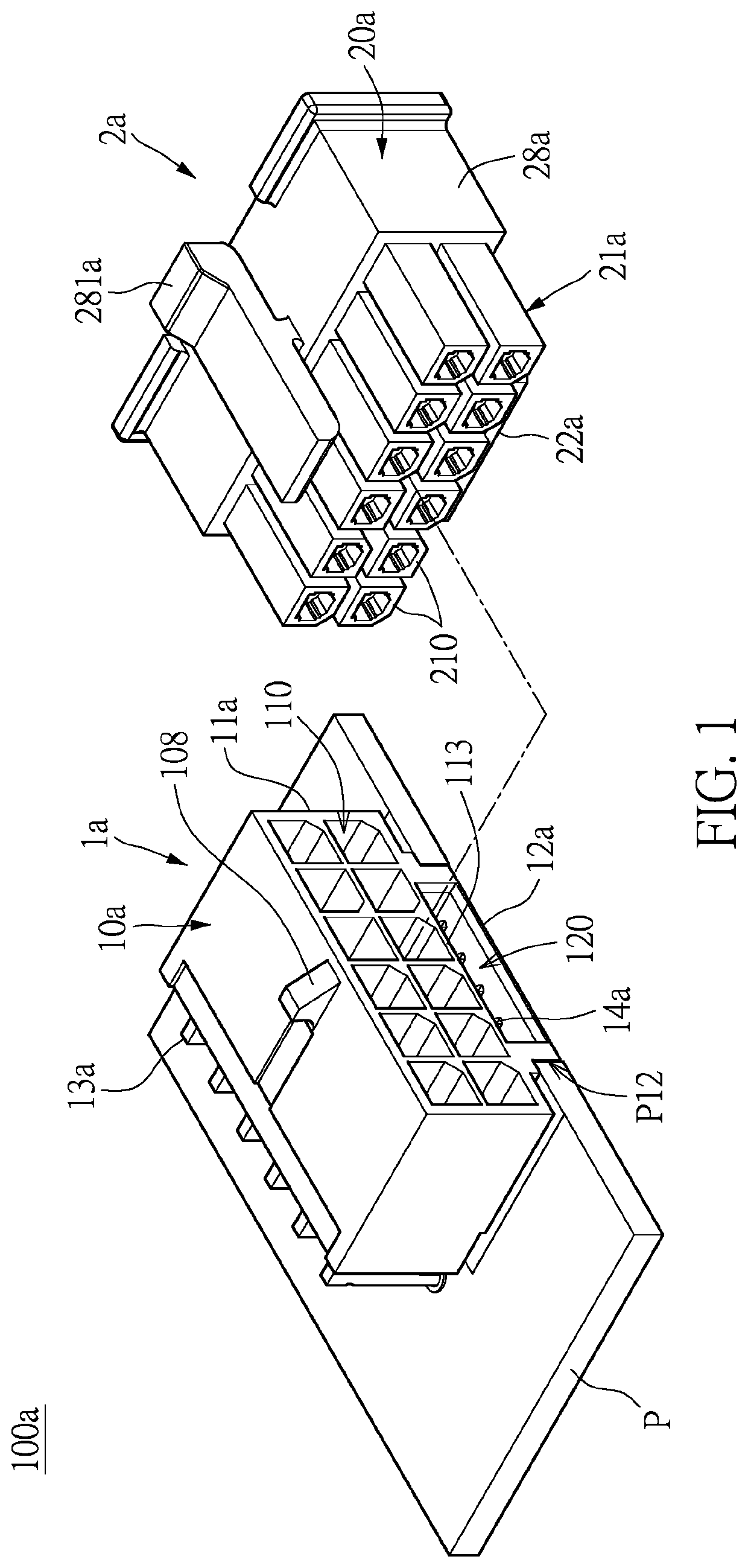
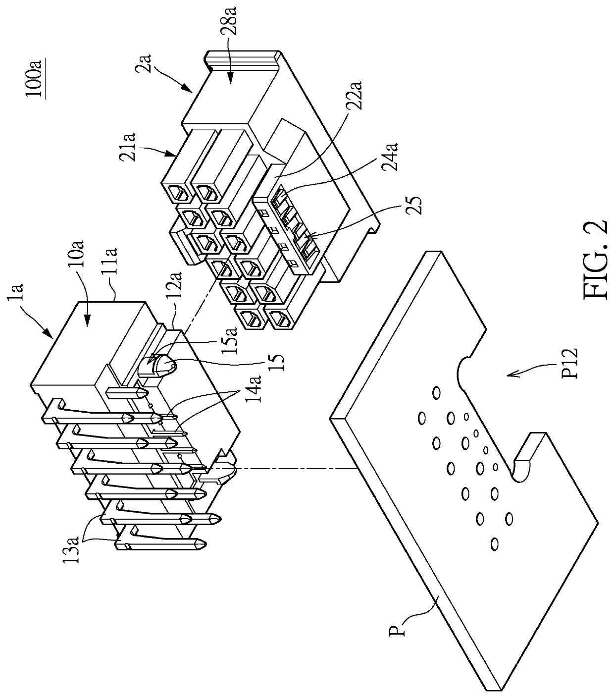
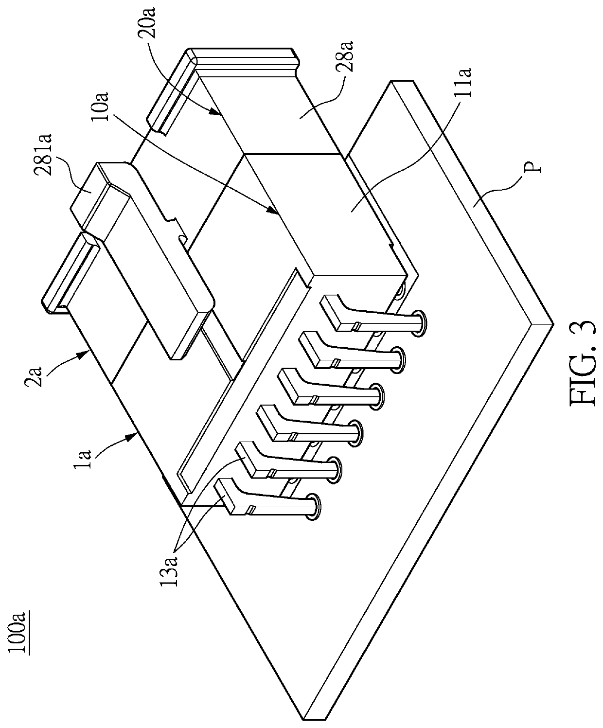
[0033]Referring to FIGS. 1 to 4, a first embodiment of the present disclosure provides a wire-to-board connector assembly 100a, which includes a board-end connector 1a and a wire-end connector 2a. The wire-end connector 2a is capable of being plugged into the board-end connector 1a to form the wire-to-board connector assembly 100a. The board-end connector 1a includes a board-end insulating housing 10a, a plurality of board-end terminals 13a, and a plurality of board-end signal terminals 14a. The wire-end connector 2a includes a wire-end insulating housing 20a, a plurality of wire-end terminals 23a, and a plurality of wire-end signal terminals 24a.

[0034]The board-end insulating housing 10a has a board-end power mating section 11a and a board-end signal mating section 12a, in which the board-end signal mating section 12a is located on one side of the board-end power mating section 11a and has a long signal slot 120. The board-end terminals 13a are accommodated in the board-end power ...

second embodiment

[0047]As shown in FIG. 5, FIG. 5 is a perspective exploded view of a wire-to-board connector assembly 100a′ according to a second embodiment of the present disclosure. The difference from the first embodiment is that, the board-end power mating section 11a has a plurality of independent slots 110 and 119. One of the plurality of independent slots, i.e., the independent slot 119, accommodates at least two of the plurality of board-end terminals 13a. In other words, the independent slot 119 is equivalent to a combination of the plurality of independent slots 110, so that an area of an opening (i.e., an area of the hole) of the independent slot 119 is greater than or equal to an area of an opening of the two independent slots 110 each accommodating one single board-end terminal 13a. Therefore, the anti-misinsertion function can be provided.

[0048]The wire-end signal mating section 22a has a long accommodating section, the long accommodating section extends forwardly from the body base 2...

third embodiment

[0049]In FIG. 6 and FIG. 7, a wire-to-board connector assembly 100b of this embodiment is shown. Similar to the previous embodiment, a board-end power mating section 11b of a board-end connector 1b is connected to a board-end signal mating section 12b. The board-end power mating section 11b has the plurality of independent slots 110, and at least one of the independent slots 110 and the long signal slot 120 have a common wall 113. In this embodiment, the common wall 113 has at least one positioning groove 123. In other words, at least one of the plurality of independent slots 110 is in communication with the long signal slot 120. The common wall 113 and the positioning groove 123 can also provide the anti-misinsertion function.

[0050]Correspondingly, the wire-end insulating housing 20b of the wire-end connector 2b has a body base 28b, a wire-end power mating section 21b, and a wire-end signal mating section 22b. The wire-end power mating section 21b extends forwardly from the body ba...


PUM


Abstract

A board-end connector and a wire-end connector capable of being engaged with each other to form a wire-to-board connector assembly are provided. The board-end connector includes a board-end insulating housing, a plurality of board-end terminals, and a plurality of board-end signal terminals. The board-end insulating housing has a board-end power mating section and a board-end signal mating section. The board-end signal mating section is located on one side of the board-end power mating section and has a long signal slot. The plurality of board-end terminals are accommodated in the board-end power mating section. The plurality of board-end signal terminals are accommodated in the long signal slot of the board-end signal mating section.

Description

CROSS-REFERENCE TO RELATED PATENT APPLICATION[0001]This application claims priority to the U.S. Provisional Patent Application Ser. No. 63 / 020,551 filed on May 6, 2020, which application is incorporated herein by reference in its entirety.[0002]Some references, which may include patents, patent applications and various publications, may be cited and discussed in the description of this disclosure. The citation and / or discussion of such references is provided merely to clarify the description of the present disclosure and is not an admission that any such reference is “prior art” to the disclosure described herein. All references cited and discussed in this specification are incorporated herein by reference in their entireties and to the same extent as if each reference was individually incorporated by reference.FIELD OF THE DISCLOSURE[0003]The present disclosure relates to a board-end connector and a wire-end connector, and more particularly to a connector that is capable of simulta...

Claims


Application Information

Patent Timeline
IPC IPC(8): H01R12/75H01R13/642
CPCH01R12/75H01R13/642H01R12/724H01R13/502H01R13/02H01R27/02H01R12/721H01R12/727H01R12/7088
Inventor CHEN, SUNG-YU
Owner CHEN SUNG YU
Features
  • Generate Ideas
  • Intellectual Property
  • Life Sciences
  • Materials
  • Tech Scout
  • Unparalleled Data Quality
  • Higher Quality Content
  • 60% Fewer Hallucinations
Learn More