

Piezoelectric pump
a piezoelectric pump and pump body technology, applied in the direction of pump components, positive displacement liquid engines, liquid fuel engine components, etc., can solve the problems of deteriorating the function of the valve, damage to the valve repeatedly colliding with the edge of the outlet, etc., and achieve the effect of reducing the reliability of the piezoelectric pump
- Summary
- Abstract
- Description
- Claims
- Application Information
AI Technical Summary
Benefits of technology
Problems solved by technology
Method used
Image

Examples
embodiment 1
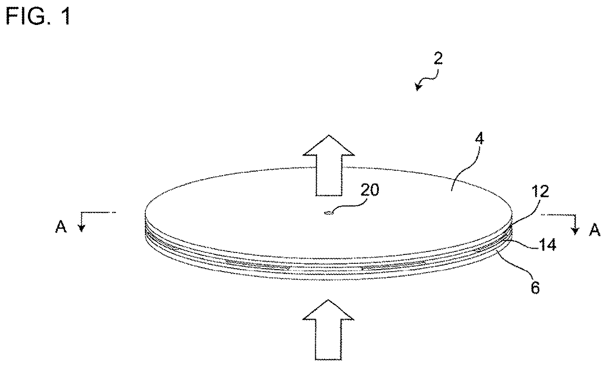
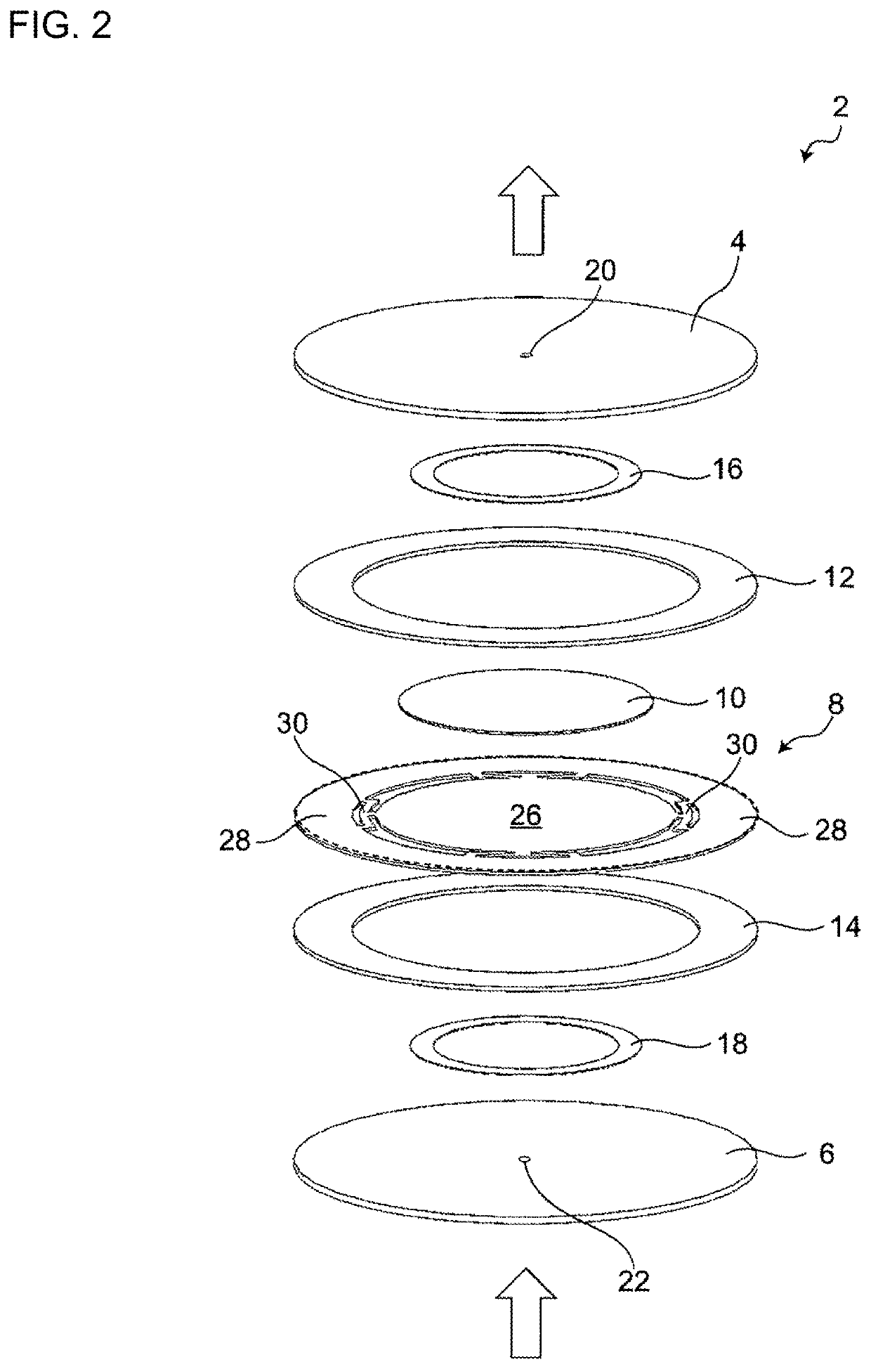
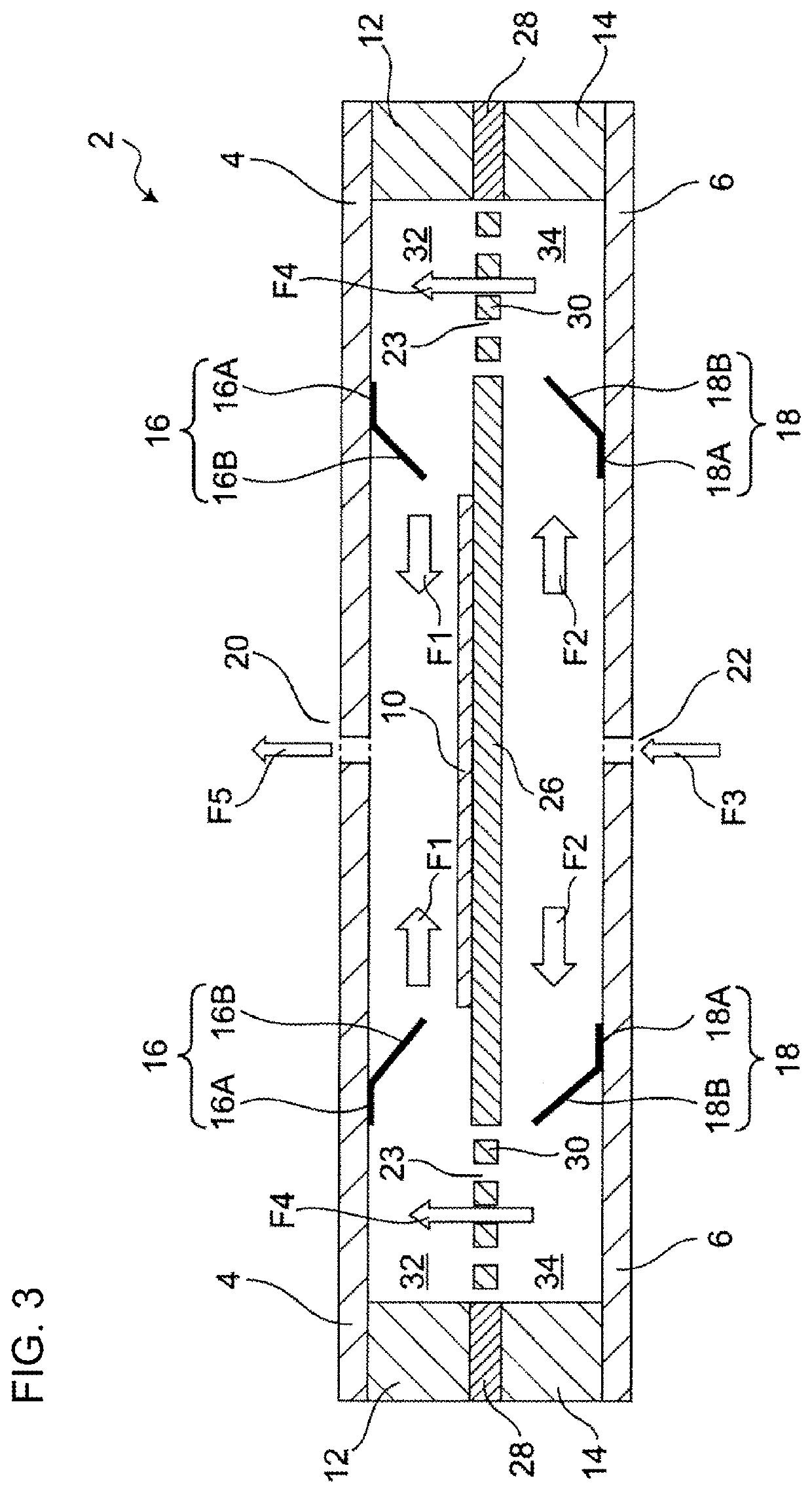
[0045]FIGS. 1 to 3 illustrate a schematic configuration of a piezoelectric pump 2 according to Embodiment 1. FIG. 1 is a perspective view of the piezoelectric pump 2 according to Embodiment 1. FIG. 2 is an exploded perspective view of the piezoelectric pump 2. FIG. 3 is a vertical sectional view (a sectional view taken along line A-A in FIG. 1) of the piezoelectric pump 2.
[0046]The piezoelectric pump 2 is a pump apparatus that transports air by using a piezoelectric device 10 (see FIGS. 2 and 3) (the piezoelectric pump 2 may also be referred to as “microblower”, “micropump”, or the like). The piezoelectric pump 2 suctions air through a second opening 22 as an inlet and discharges air through a first opening 20 as an outlet while the piezoelectric device 10 is vibrated at a high speed. As illustrated in FIGS. 1 to 3, the first opening 20 is provided in the front face of the piezoelectric pump 2, and the second opening 22 is provided in the back face of the piezoelectric pump 2.
[0047]...
embodiments 2 to 4
[0101]Piezoelectric pumps according to Embodiments 2 to 4 of the present disclosure will now be described. In Embodiments 2 to 4, differences from Embodiment 1 will be discussed mainly. Furthermore, the description already given in Embodiment 1 is omitted.
[0102]FIG. 10 is a vertical sectional view of a piezoelectric pump 60 according to Embodiment 2 and illustrates a schematic configuration thereof. FIG. 11 is a vertical sectional view of a piezoelectric pump 70 according to Embodiment 3 and illustrates a schematic configuration thereof. FIG. 12 is a vertical sectional view of a piezoelectric pump 80 according to Embodiment 4 and illustrates a schematic configuration thereof.
[0103]In Embodiments 2 to 4, factors such as the position and orientation of the first valve provided in the first pump chamber 32 and the position and orientation of the second valve provided in the second pump chamber 34 are different from those of Embodiment 1.
embodiment 2
[0104]As illustrated in FIG. 10, the piezoelectric pump 60 according to Embodiment 2 includes a first valve 62 and a second valve 64. As with the case of Embodiment 1, the first valve 62 is fixed to the first faceplate 4, and the second valve 64 is fixed to the second faceplate 6. However, the positional relationship between the fixed portion and the movable portion of each of the valves 62 and 64 is different.
[0105]Specifically, the first valve 62 includes a first fixed portion 62A and a first movable portion 62B. The first movable portion 62B is positioned on the outer side with respect to the first fixed portion 62A in plan view. The second valve 64 includes a second fixed portion 64A and a second movable portion 64B. The second movable portion 64B is positioned on the inner side with respect to the second fixed portion 64A in plan view. That is, the first valve 62 suppresses an air current flowing inward in plan view, whereas the second valve 64 suppresses an air current flowing...
PUM
 Abstract
Description
Claims
Application Information