Check patentability & draft patents in minutes with Patsnap Eureka AI!

Continuous wave time of flight system

a flight system and wave time technology, applied in the field of range imaging systems, can solve the problems of significant reduction in imaging accuracy, faster overall operation, and lower overall energy consumption, and achieve the effects of reducing overall energy consumption, and improving imaging accuracy

Pending Publication Date: 2021-11-18
ANALOG DEVICES INT UNLTD
View PDF3 Cites 0 Cited by
  • Summary
  • Abstract
  • Description
  • Claims
  • Application Information

AI Technical Summary

Benefits of technology

The present patent is about a new and improved camera system that can measure distance to an object by emitting laser light and capturing images of the reflected light. The system uses two different frequencies for laser modulation, which allows for faster and more accurate distance measurements. The system is designed to operate at lower energy levels and faster speeds compared to previous continuous wave time of flight systems, without sacrificing accuracy. The method for achieving the lower power mode involves driving the laser in steps and outputting laser light for a shorter period of time than the same steps during normal operation.

Problems solved by technology

This results in lower overall energy consumption, and potentially also faster overall operation, compared with previous continuous wave time of flight systems, without any significant reduction in accuracy of imaging.

Method used


Image

  • Continuous wave time of flight system
  • Continuous wave time of flight system
  • Continuous wave time of flight system

Examples


example 10

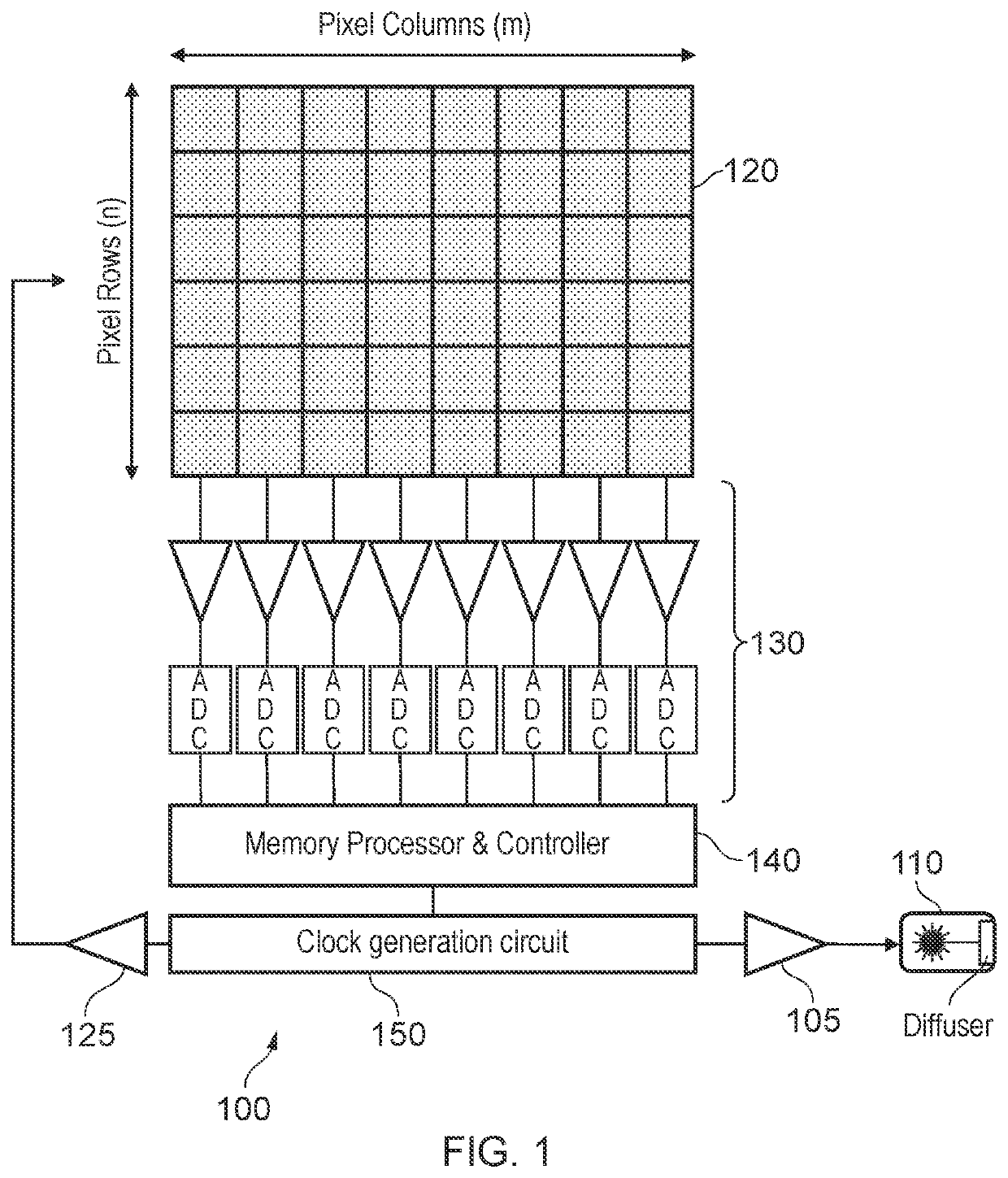
[0127 provides a system according to one or more of the preceding and / or following examples wherein the image acquisition system comprises one or more amplifiers for amplifying signals read from the imaging sensor, and wherein the image acquisition system is configured to: operate at least some of the one or more amplifiers in a first power mode when acquiring the first set of charge samples; and operate at least some of the one or more amplifiers in a second power mode when acquiring the second set of charge samples, wherein the first power mode is lower than the second power mode.

[0128]Example 11 provides a system according to one or more of the preceding and / or following examples wherein the image acquisition system comprises one or more analog-to-digital converters, ADC, for converting analog signals read from the imaging sensor to digital signals, and wherein the image acquisition system is configured to operate at least some of the ADCs in a first power mode when determining a...

example 20

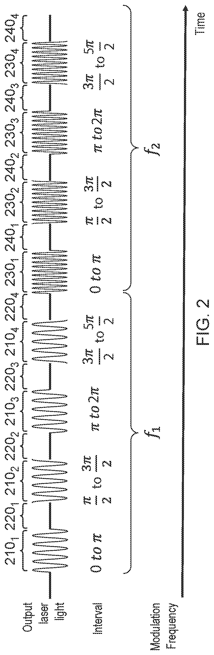
[0137 provides a system according to one or more of the preceding and / or following examples, further configured to obtain the first plurality of charge samples by: driving the laser to emit first laser light modulated with the first modulation signal for a period of time; controlling, during the period of time, the imaging sensor to accumulate charge on a first set of imaging pixels for a first portion of the modulation signal; controlling, during the period of time, the imaging sensor to accumulate charge on a second set of imaging pixels for a second portion of the modulation signal, wherein the second portion is the same duration of the modulation signal as the first portion but with a different phase offset; and at the conclusion of the period of time, reading out the first set of imaging pixels to obtain one of the first plurality of charge samples and reading out the second set of imaging pixels to obtain another of the first plurality of charge samples.

[0138]Variations and Im...


PUM


Abstract

Systems and methods for a lower energy / faster time of flight camera system configured to measure distance to an object. The system is configured to emit laser light modulated with a first frequency and image light reflected by an object in order to determine a first phase difference between the emitted and reflected light. The system emits laser light modulated with a second frequency and images light reflected by the object to determine a second phase difference between the emitted and reflected light. The distance to the object is determined using the first and second phase differences. The system is arranged to operate at lower energy for obtaining the first phase difference compared with the operation to obtain the second phase difference. This results in lower overall energy consumption and faster overall operation without any significant reduction in accuracy of imaging.

Description

PRIORITY DATA[0001]This application claims the benefit pursuant to 35 U.S.C § 119(e) of U.S. Provisional Patent Application Ser. No. 63 / 025,393 filed on May 15, 2020, entitled “CONTINUOUS WAVE TIME OF FLIGHT SYSTEM”, the entirety of which is incorporated by reference herein.BACKGROUND[0002]Time-of-flight (ToF) camera systems are range imaging systems that resolve the distance between the camera and an object by measuring the round trip of light emitted from the ToF camera system. The systems typically comprise a light source (such as a laser or LED), a light source driver to control the emission of light from the light source, an image sensor to image light reflected by the subject, an image sensor driver to control the operation of the image sensor, optics to shape the light emitted from the light source and to focus light reflected by the object onto the image sensor, and a computation unit configured to determine the distance to the object based on the emitted light and the corre...

Claims


Application Information

Patent Timeline
IPC IPC(8): G01S17/894H04N5/369H04N5/347H04N5/345H04N5/378G01S7/481G01B11/22G01S7/4911
CPCG01S17/894H04N5/3698H04N5/347H04N5/345G01S7/4911G01S7/4814G01B11/22G01S7/4816H04N5/378G01S17/32G01S7/4913G01S7/481H04N25/78G01S7/491G01S17/36H04N25/44H04N25/46H04N25/75H04N25/709
Inventor HURWITZ, JONATHAN EPHRAIM DAVIDBALICKI, KRYSTIANENGLISH, EOIN E.
Owner ANALOG DEVICES INT UNLTD
Features
  • R&D
  • Intellectual Property
  • Life Sciences
  • Materials
  • Tech Scout
  • Unparalleled Data Quality
  • Higher Quality Content
  • 60% Fewer Hallucinations
Learn More