Image projecting systems and methods

a projecting system and image technology, applied in the field of image projecting systems and methods, can solve the problems of difficult positioning of the print of a fabric, difficulty in storing conventional printed digital patterns, and inability to reuse the other sizes of the pattern, etc., and achieve the effect of convenient digital storage and fully reusabl

Pending Publication Date: 2021-11-18
DITTOPATTERNS LLC
View PDF0 Cites 6 Cited by
  • Summary
  • Abstract
  • Description
  • Claims
  • Application Information

AI Technical Summary

Benefits of technology

[0008]In accordance with one aspect of the invention, the present disclosure discloses a projection system designed to accurately project all required sewing pattern lines and notations and even instructions directly onto the material to be sewn. Patterns may be projected onto many different types of materials such as fabric, canvas, felt, leather, paper, carpet, etc. The projected patterns are easily digitally storable, fully reusable, and do not obstruct view of the fabric or other material being sewn.

Problems solved by technology

Once the proper size is cut out from the full pattern sheet, it is typically not possible to reuse the other sizes in the pattern.
But conventional printed digital patterns still suffer from some of the problems of conventional paper patterns because they still require paper.
For example, paper patterns (traditional paper or digital) make it difficult to position the print of a fabric (such as, for example, a flower print) in a specific location because the pattern paper covers the print.
Moreover, traditional paper as well as printed digital patterns are cumbersome, easily ripped, and difficult to store.
However, in conventional cutting mats, pieces of fabric could slide or move during this cutting process.

Method used


Image

  • Image projecting systems and methods
  • Image projecting systems and methods
  • Image projecting systems and methods

Examples


Embodiment Construction

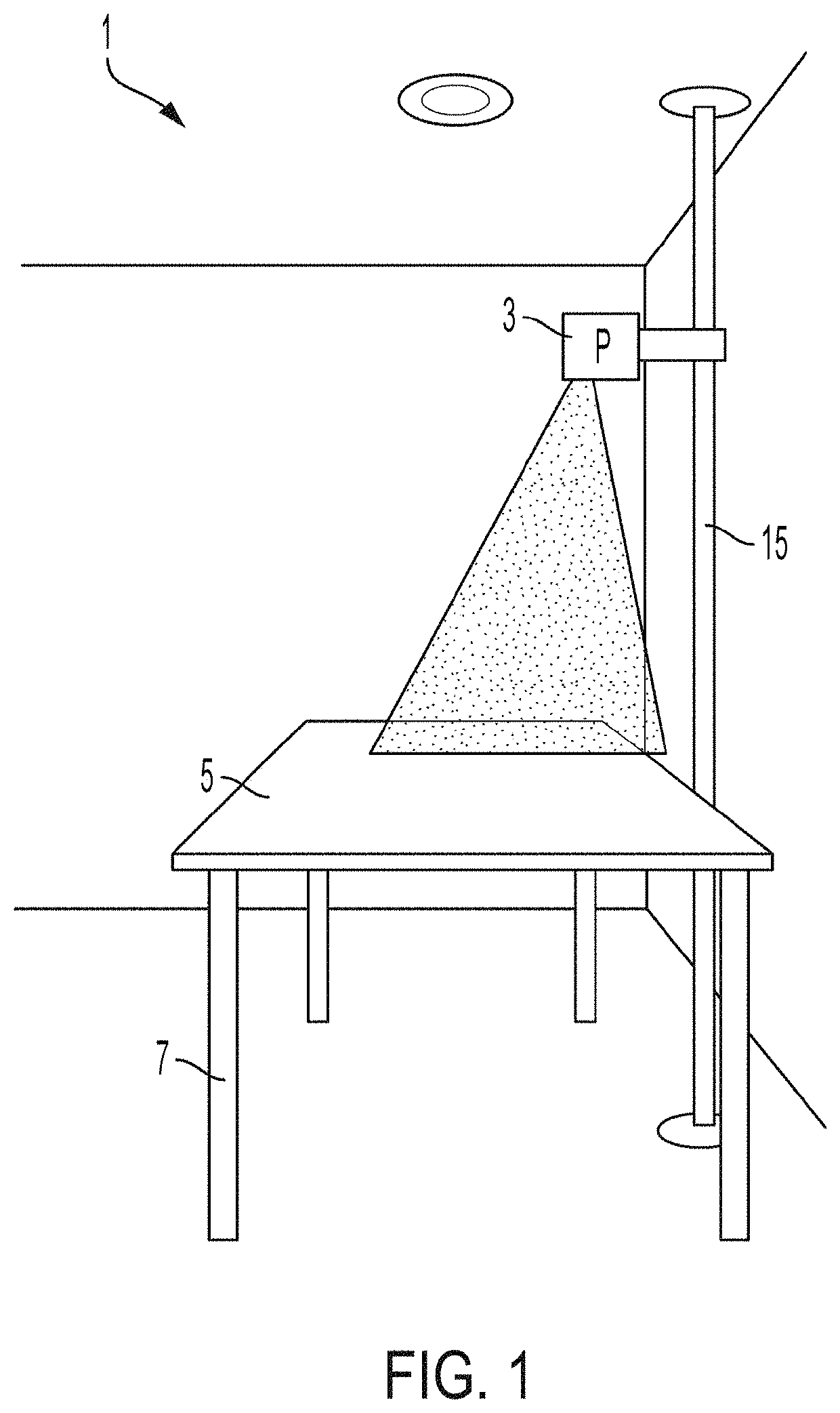
[0059]FIG. 1 illustrates a perspective view of a projection system 1 for projecting sewing patterns onto fabric. The system 1 includes a projector 3 that receives data representing sewing patterns and projects the sewing patterns onto fabric disposed on a horizontal surface 5 (top surface of table 7) vertically below the projector 3. The projection system 1 is generally related to a concept described in U.S. patent application Ser. No. 15 / 853,807, filed on Dec. 24, 2017, now U.S. Pat. No. 10,750,810, which is hereby incorporated by reference in its entirety. Also, U.S. patent application Ser. No. 16 / 350,932, now U.S. Pat. No. 11,003,903 concerns formatting electronic sewing patterns and making them available to customers and is also incorporated by reference. Although for ease of explanation inventions are disclosed herein in the context of sewing patterns, some if not all of the inventions disclosed herein have applicability in contexts other than sewing patterns and, thus, those i...


PUM


Abstract

A projection system for projecting sewing patterns onto a surface comprises a vertical beam, a projector, and a cart. The vertical beam includes (a) a floor engaging portion at a bottom end and (b) a ceiling engaging portion at a top end, the ceiling engaging portion being vertically movable with respect to the floor engaging portion such that, when in use, the floor engaging portion and the ceiling engaging portion engage a floor and a ceiling, respectively, to anchor the projection system adjacent the surface. The projector is configured to receive data representing the sewing patterns and to project the sewing patterns. The cart is operably attached to the projector and slidably attached to the vertical beam, wherein sliding the cart vertically adjusts a height of the projector above the surface.

Description

[0001]This patent application claims priority to and benefit of U.S. Provisional Application No. 63 / 023,750, filed May 12, 2020, and U.S. Provisional Application No. 63 / 129,336, filed Dec. 22, 2020, which are all incorporated herein by reference.BACKGROUND[0002]In sewing and fashion design, a pattern is the template from which the parts of a garment or other item are traced onto fabric before being cut out and assembled. Conventional patterns are usually made of paper, typically tissue paper, tracing paper, printer paper, and the like. Typically, a sewist (i.e., the artist who sews the item) obtains a sewing pattern packet that includes pattern pieces printed on paper.[0003]The larger pattern may be cut into the pattern pieces corresponding to the different parts (e.g., front, sleeve, pocket, etc.) of the item. The printed pattern pieces, after being cut out, may then be either pinned or weighted down onto the fabric. The sewist may then cut along the outline of each paper pattern p...

Claims


Application Information

Patent Timeline
Patent Type & Authority Applications(United States)
IPC IPC(8): G03B21/14D05B35/12D05B3/24F16M11/04G01C9/34
CPCG03B21/145D05B35/12G01C9/34F16M11/046D05B3/24D05B79/00G01C9/28
Inventor MCNEELEY, CAROLYNSZPAK, JAMES EDWARDYE, DANWEIDELLINGER, SHAWNDEMORE, ANTHONYCAUTION, STEPHENKARNADI, DANIELIZEN, STEVEROHLER, DAVID
Owner DITTOPATTERNS LLC
Why Eureka
Try Eureka