
Distributed energy resource system design and operation

Pending Publication Date: 2021-11-18
SCHLUMBERGER TECH CORP
View PDF5 Cites 1 Cited by
  • Summary
  • Abstract
  • Description
  • Claims
  • Application Information

AI Technical Summary

Benefits of technology

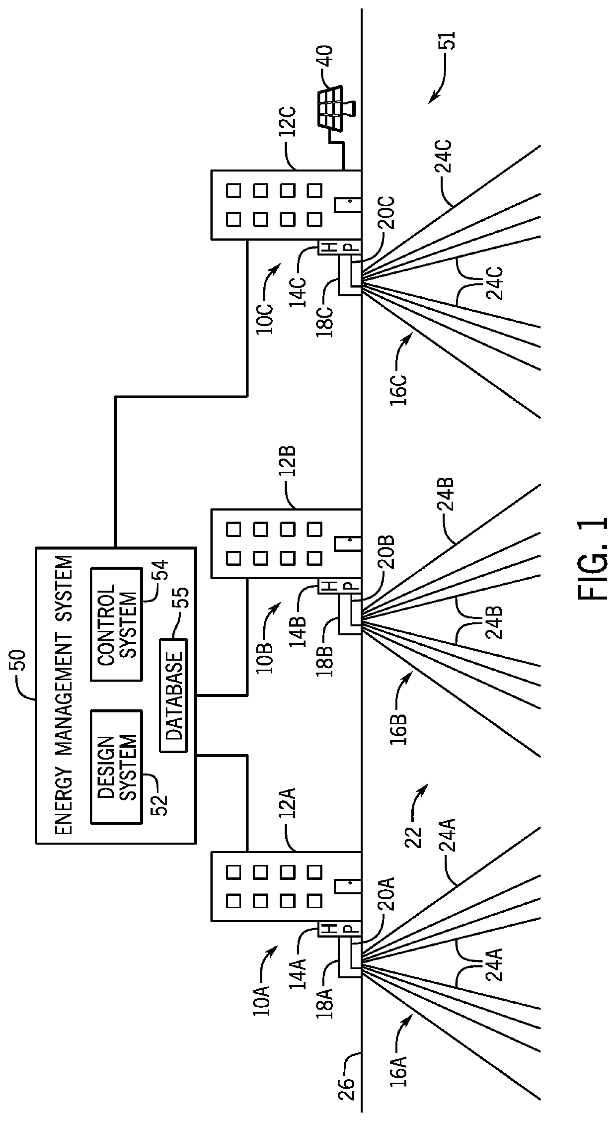
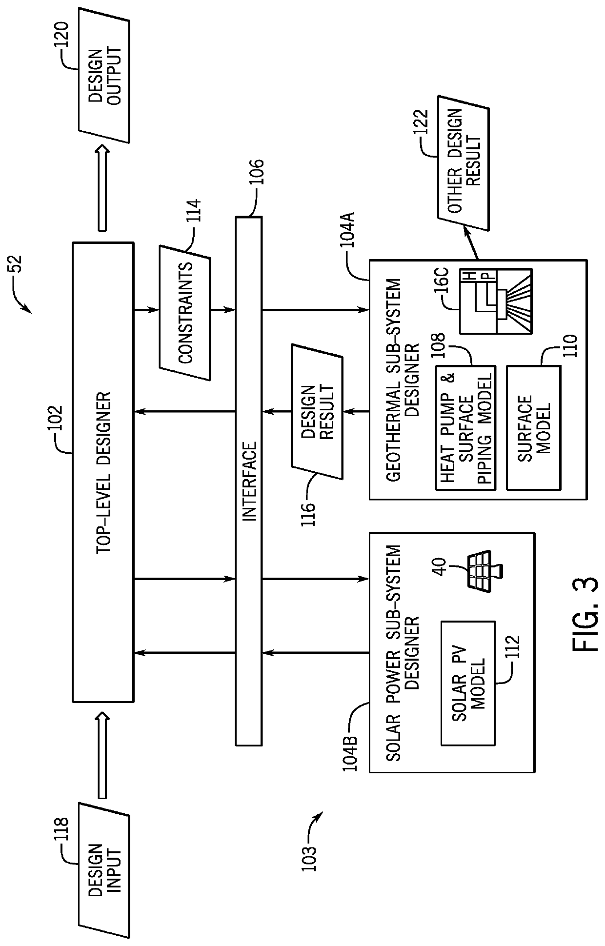
The invention is an energy management system for a distributed energy resource system, which includes a design system and a hierarchical optimization-based control system. The design system coordinates decentralized bottom-level design routines for individual energy resources to seek a global design at a top level based on design input for the distributed energy resource system that satisfies an energy demand of a target deployment location within a confidence level. The detail designs of multiple local energy sub-systems are generated by the multiple bottom-level designers, with the top-level designer updating the global design based on at least a portion of the detailed designs. The hierarchical optimization-based control system includes a primary controller that determines a long-term operational schedule based on long-term constraints and future events at a first level, one or more secondary controllers that control daily or short-term orchestrations of the distributed energy resource system at a second level, and multiple tertiary controllers that rapidly adjust various hardware at a third level. The technical effects of this invention are improved energy management for distributed energy resource systems through efficient energy optimization and coordination of multiple energy sub-systems at different levels of the system.

Problems solved by technology

As explained above, integration of different energy resources (e.g., electrical, geothermal, solar, wind power, etc.) may be challenging for a distributed energy resource system design and / or operation.
Such results may be accompanied by corresponding uncertainties.

Method used


Image

  • Distributed energy resource system design and operation
  • Distributed energy resource system design and operation
  • Distributed energy resource system design and operation

Examples


Embodiment Construction

[0015]Specific embodiments of the present disclosure are described below. In an effort to provide a concise description of these embodiments, all features of an actual implementation may not be described in the specification. It should be appreciated that in the development of any such actual implementation, as in any engineering or design project, numerous implementation-specific decisions must be made to achieve the developers' specific goals, such as compliance with system-related and business-related constraints, which may vary from one implementation to another. Moreover, it should be appreciated that such a development effort might be complex and time-consuming, but would nevertheless be a routine undertaking of design, fabrication, and manufacture for those of ordinary skill having the benefit of this disclosure.

[0016]Example methods, devices, systems, and applications are described herein. It should be understood that the word “example” is used here to mean serving as an exa...


PUM


Abstract

An energy management system for enhancing design and operation of a distributed energy resource system includes a two-level design system and a hierarchical optimization-based control system. The two-level design system includes a top-level designer configured to coordinate decentralized bottom-level designers for individual energy resources to seek a global target for the designed distributed energy resource system that satisfies the energy demand of a target deployment location within a confidence level, and multiple bottom-level designers configured to enhance detailed designs of local energy sub-systems. The hierarchical optimization-based control system include a primary controller configured to determine a long-term operational schedule based on long-term constraints and future events at a first level, one or more secondary controllers configured to control daily orchestrations of the distributed energy resource system during operation at a second level, and multiple tertiary controllers and aggregators configured to rapidly adjust various hardware at a third level.

Description

CROSS REFERENCE TO RELATED APPLICATION[0001]This application claims priority from and the benefit of U.S. Provisional Application Ser. No. 63 / 024,798 entitled “Optimal Design and Operation of a Distributed Energy Resource System”, filed May 14, 2020, which is hereby incorporated by reference in its entirety.BACKGROUND[0002]The present disclosure relates generally to model-based design and operation for a distributed energy resource system.[0003]This section is intended to introduce the reader to various aspects of art that may be related to various aspects of the present disclosure, which are described below. This discussion is believed to be helpful in providing the reader with background information to facilitate a better understanding of the various aspects of the present disclosure. Accordingly, it should be understood that these statements are to be read in this light, and not as admissions of prior art.[0004]Distributed energy resource systems may include a variety of renewabl...

Claims


Application Information

Patent Timeline
IPC IPC(8): G06Q50/06G06Q10/06G05B15/02H02J3/38
CPCG06Q50/06H02J3/381G05B15/02G06Q10/067Y04S10/12Y02E40/70H02J2203/20Y02E60/00Y02P80/20Y02P80/10Y04S10/50Y04S40/20G06Q10/0631G05B13/02
Inventor DA MATA CECILIO, INESSIMON, MATTHIEUBITTLESTON, SIMONTHIERRY, SYLVAIN
Owner SCHLUMBERGER TECH CORP
Learn More