Electronic device having antennas

a technology of electronic devices and antennas, which is applied in the direction of independent non-interfering antenna combinations, substation equipment, transmission, etc., can solve the problems of space limitation problems of some antennas operating in the sub-6 band, interference between the mmwave antenna module and the metal rim, and difficulty in releasing heat (disassembly, discharge) to the outside, so as to maintain antenna performance and maintain stable communication performance , the effect of minimizing the space of the antenna arrangemen

Active Publication Date: 2021-11-18
LG ELECTRONICS INC
View PDF0 Cites 14 Cited by
  • Summary
  • Abstract
  • Description
  • Claims
  • Application Information

AI Technical Summary

Benefits of technology

[0043]According to the present disclosure, an antenna structure capable of maintaining antenna performance in a rollable device can be provided, thereby maintaining stable communication performance even when a display region is expanded or reduced.
[0044]According to the present disclosure, an antenna structure capable of securing antenna performance in a display structure with a minimized bezel region in a rollable device can be provided, thereby minimizing an antenna arrangement space.
[0045]According to the present disclosure, antenna performance can be improved without changing a mechanical structure and design factors of an electronic device such as a rollable device.
[0046]According to the present disclosure, an antenna arrangement structure capable of minimizing radio wave interference when a user grips an electronic device can be provided.
[0047]According to the present disclosure, an mmWave antenna can be mounted on a seating portion of a metal frame when a plurality of antennas and the mmWave antenna module are disposed, thereby reducing heat generation due to RF signals.
[0048]According to the present disclosure, E-UTRAN NR Dual Connectivity (EN-DC), carrier aggregation (CA), and Multiple-input and Multi-output (MIMO) can be supported in a rollable device without changing a mechanical structure and a design shape.

Problems solved by technology

However, when existing LTE antennas and some 5G antennas are already provided in the form of metal rims on side surfaces of the electronic device, a space limitation problem may occur for some of the antennas operating in the Sub-6 band.
In this case, there is a problem that interference may occur between the mmWave antenna module and the metal rims for the LTE antenna and the 5G Sub-6 antenna.
In this regard, there is a problem that heat is difficult to be released (dissipated, discharged) to outside by a mechanical structure supporting the mmWave antenna module.

Method used


Image

  • Electronic device having antennas
  • Electronic device having antennas
  • Electronic device having antennas

Examples


Embodiment Construction

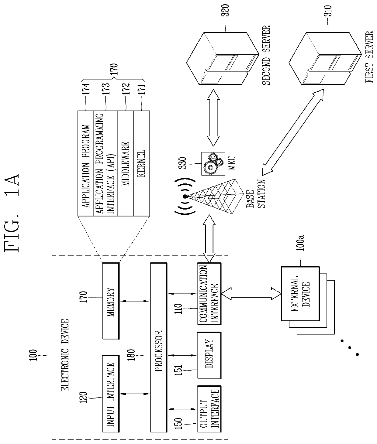
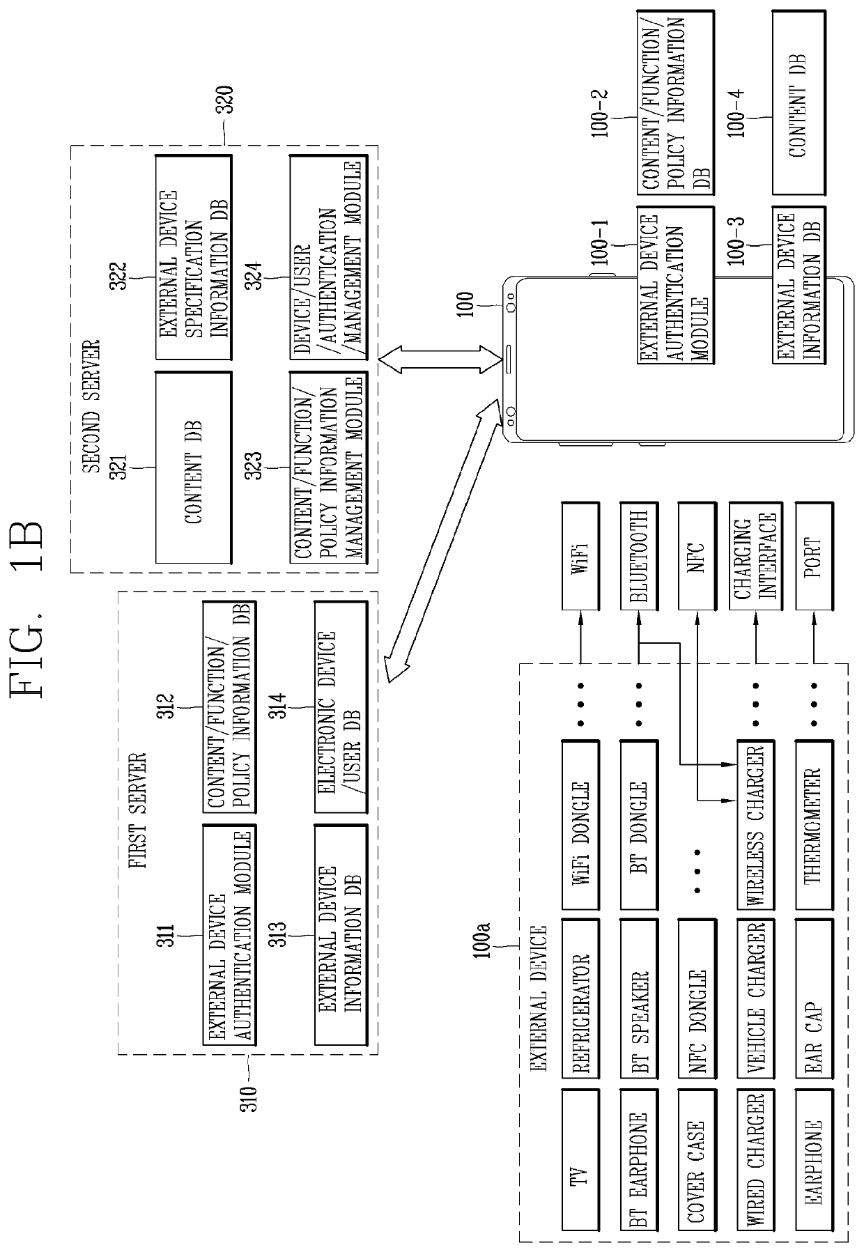
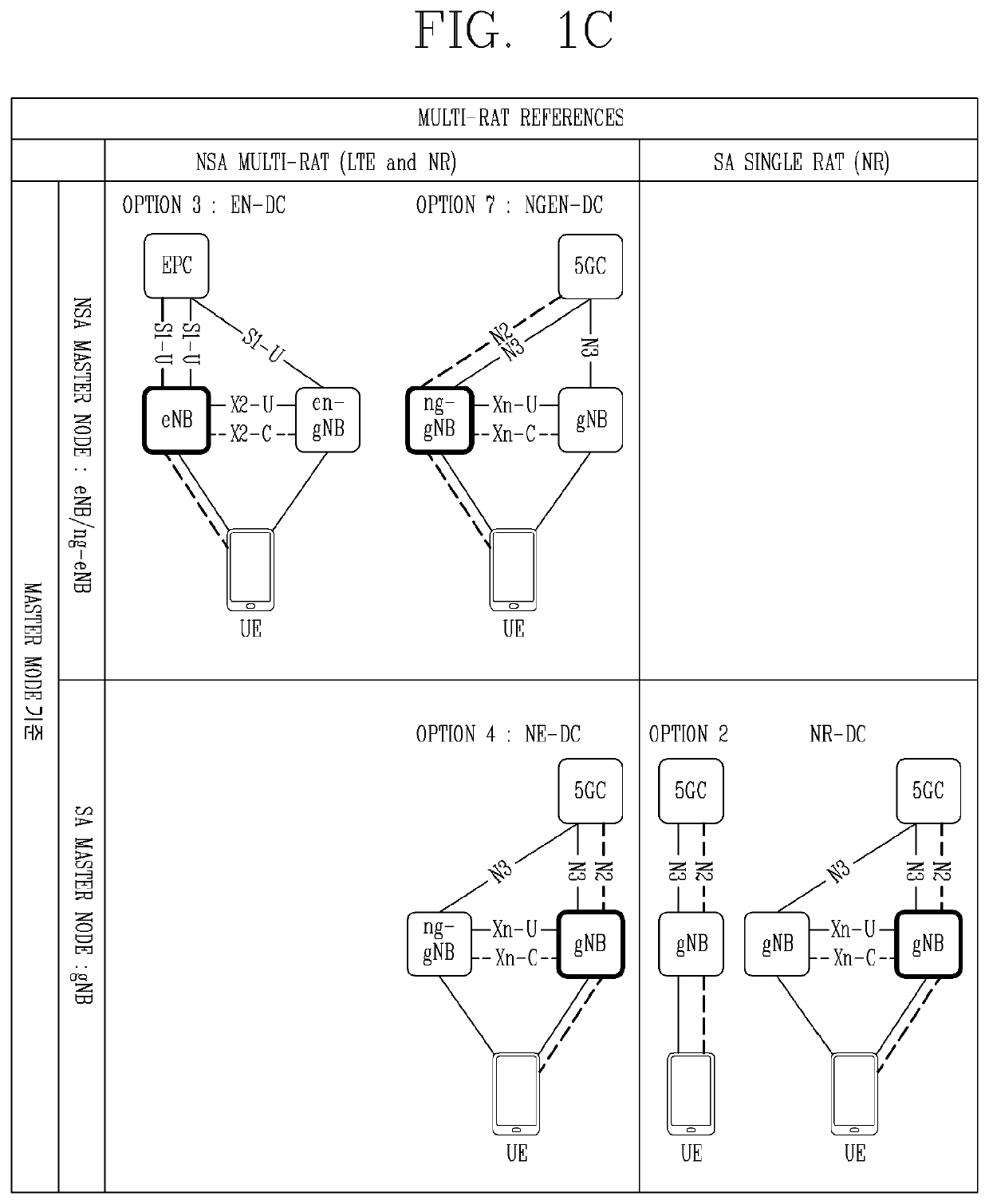
[0072]Description will now be given in detail according to exemplary embodiments disclosed herein, with reference to the accompanying drawings. For the sake of brief description with reference to the drawings, the same or equivalent components may be provided with the same or similar reference numbers, and description thereof will not be repeated. In general, a suffix such as “module” and “unit” may be used to refer to elements or components. Use of such a suffix herein is merely intended to facilitate description of the specification, and the suffix itself is not intended to give any special meaning or function. In describing the present disclosure, if a detailed explanation for a related known function or construction is considered to unnecessarily divert the gist of the present disclosure, such explanation has been omitted but would be understood by those skilled in the art. The accompanying drawings are used to help easily understand the technical idea of the present disclosure ...


PUM


Abstract

An electronic device according to one embodiment may include a conductive member antenna implemented as one of a plurality of metal rims and configured to radiate a signal, and an antenna module disposed between a metal frame and a sliding module of the electronic device, and configured to radiate a signal in a millimeter wave (mmWave) band. The sliding module may be coupled to the conductive member antenna and disposed between the conductive member antenna and a moving portion of the electronic device to operate as a slide support portion.

Description

CROSS-REFERENCE TO RELATED APPLICATIONS[0001]Pursuant to 35 U.S.C. § 119, this application claims the benefit of an earlier filing date and right of priority to International Application No. PCT / KR2020 / 006396, filed on May 15, 2020, the contents of which is incorporated by reference herein in its entirety.BACKGROUND1. Technical Field[0002]The present disclosure relates to an electronic device having antennas. One particular implementation relates to an antenna arrangement in an electronic device with a rollable or foldable device.2. Description of the Related Art[0003]Electronic devices may be divided into mobile / portable terminals and stationary terminals according to mobility. Also, the electronic device may be classified into handheld types and vehicle mount types according to whether or not a user can directly carry.[0004]Functions of electronic devices are diversified. Examples of such functions include data and voice communications, capturing images and video via a camera, rec...

Claims


Application Information

Patent Timeline
Patent Type & Authority Applications(United States)
IPC IPC(8): H01Q1/24H01Q5/307H04B7/0413H04M1/02
CPCH01Q1/243H04M1/0237H04B7/0413H01Q5/307H01Q21/28H01Q1/44H04M1/0235H04M1/026
Inventor WON, YOONJAESONG, MOONSOOHWANG, KYOUNGSUNCHOI, DEUKSUYOU, CHISANG
Owner LG ELECTRONICS INC
Why Eureka
Try Eureka