
Eureka
For R&D, Eureka makes reading and utilizing patents & technical documents easy.
Eureka AIR
Designed for self-driven R&D workflows. Generate viable solutions, solve complex R&D challenges, empower your innovation with AI.

Eureka Materials
Designed for material experts only. Revolutionize your material R&D, from search, analyze, to developing new materials.

TechResearch
Generate reliable direction feasibility study reports for your R&D in just a few steps.

TechSeek
Discover and master advanced knowledge NOW. Basics, ideas, possibilities, all at once.

TechMind
As an expert in R&D Theories, TechMind can generates customized viable solutions instantly.

TechRisk
Analyze your overall solution with one click, know your potential R&D risks in advance.

TechMonitor
Get weekly tech updates, stay abreast of the latest tech innovations and key insights.
Impact tool head
- Summary
- Abstract
- Description
- Claims
- Application Information
AI Technical Summary
Benefits of technology
Problems solved by technology
Method used
Image

Examples
Embodiment Construction
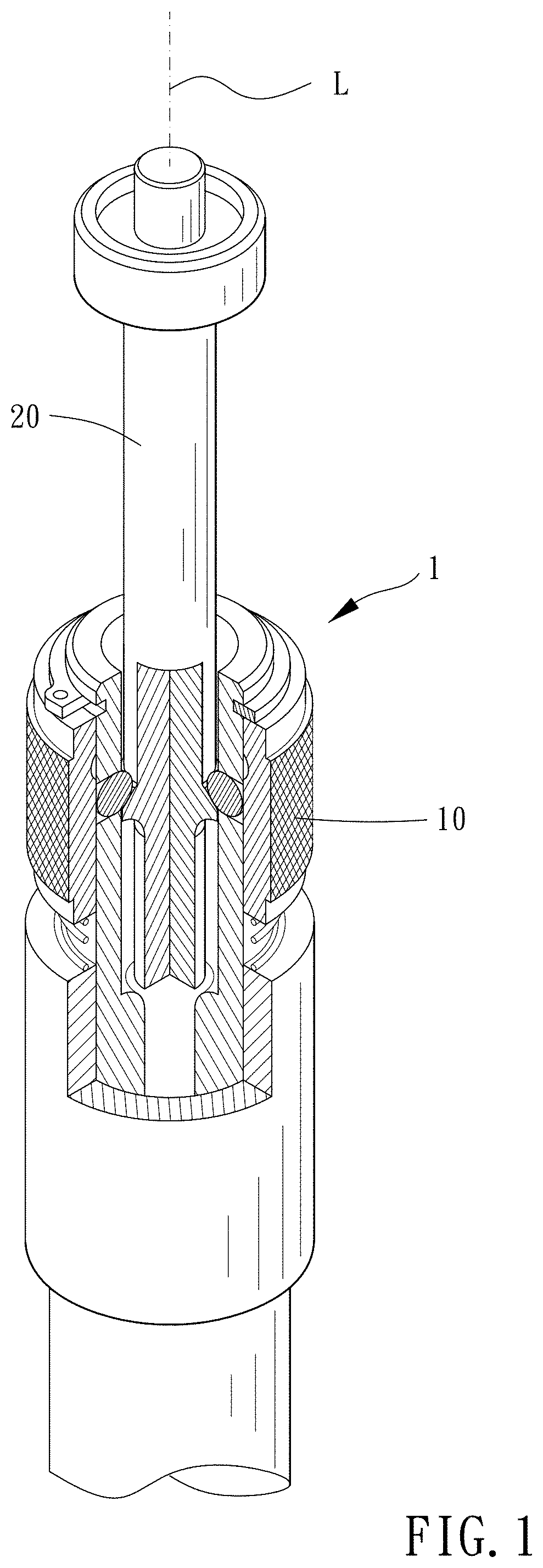
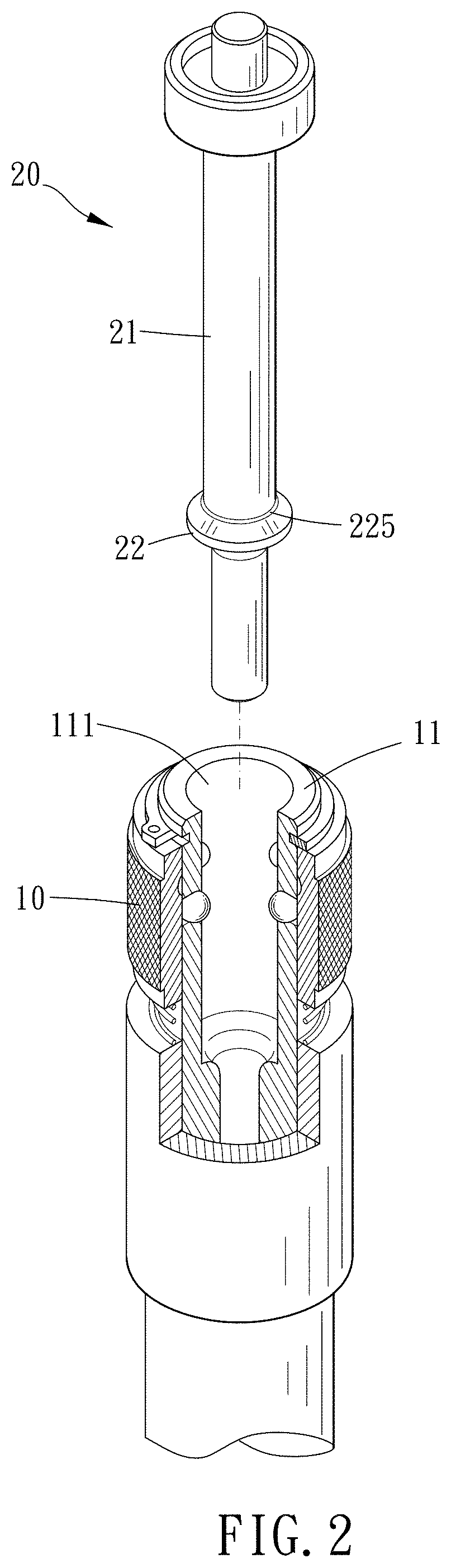
[0014]Please refer to FIGS. 1 to 8 for a preferable embodiment of the present invention. An impact tool head assembling mechanism 1 includes an engaging sleeve 10 and an impact tool head 20.
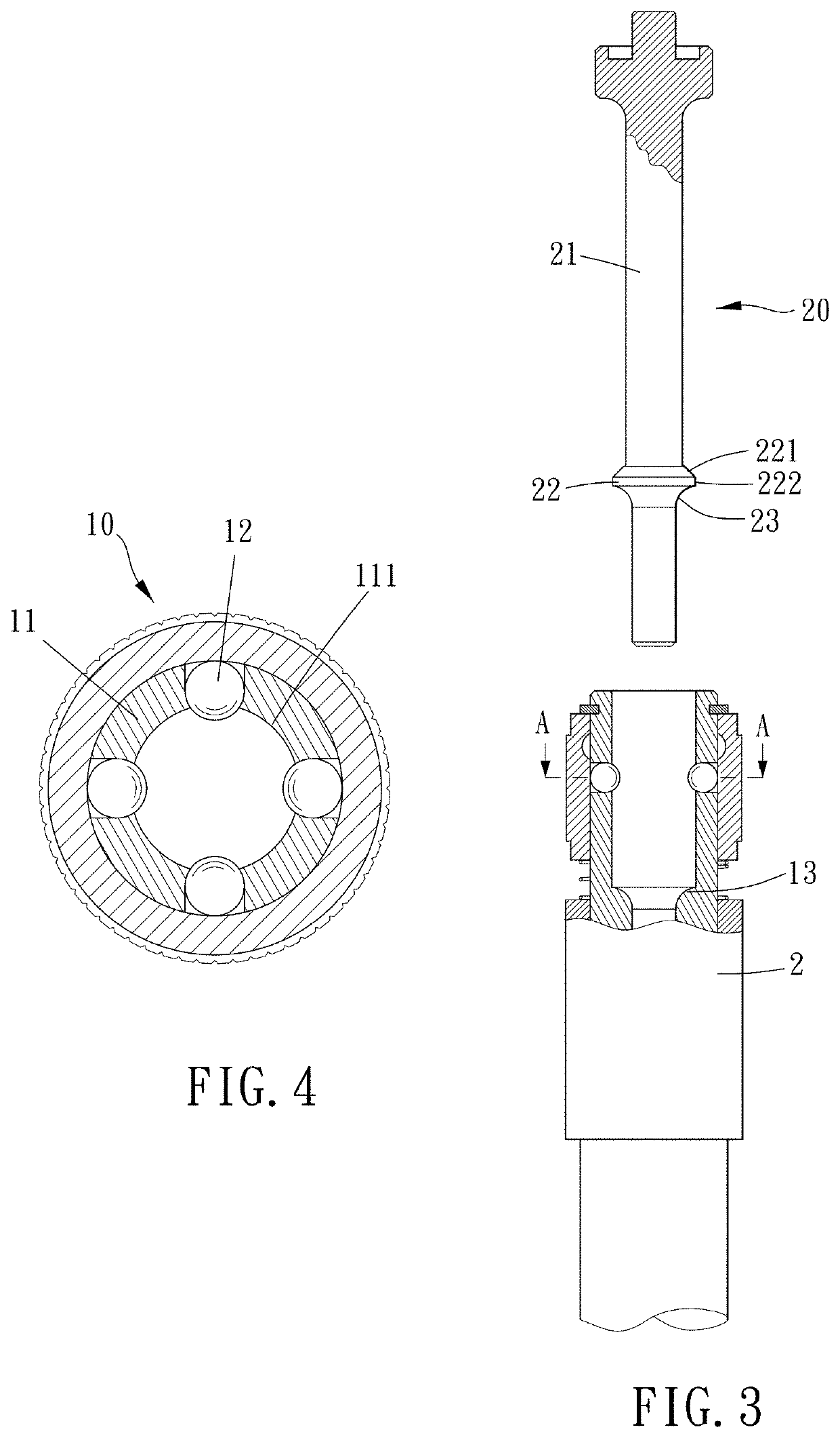
[0015]The engaging sleeve 10 is disposed on a front end of an impact tool 2 and includes a tubular wall 11 and at least one projection 12. The tubular wall 11 defines an axial direction L, and the at least one projection 12 is protrudingly and retractably disposed on an inner face 111 of the tubular wall 11. The impact tool head 20 includes a rod body 21 and a flange 22 radially protruding from the rod body 21. The flange 22 includes an inclined surface 221 facing toward the front end and an outermost peripheral edge 222, and a contact position P is defined as a position where the inclined surface 221 contact with the at least one projection 12. A reference plane F is defined as passing through the outermost peripheral edge 222 and perpendicular to the axial direction L. An included angle α betwe...
PUM
 Abstract
Description
Claims
Application Information
 - R&D Engineer
- R&D Manager
- IP Professional
- Industry Leading Data Capabilities
- Powerful AI technology
- Patent DNA Extraction
Browse by: Latest US Patents, China's latest patents, Technical Efficacy Thesaurus, Application Domain, Technology Topic, Popular Technical Reports.
© 2024 PatSnap. All rights reserved.Legal|Privacy policy|Modern Slavery Act Transparency Statement|Sitemap|About US| Contact US: help@patsnap.com