Conformal cooling devices for rotating generator elements and additive manufacturing processes for fabricating the same

a technology of additive manufacturing and generator elements, which is applied in the direction of machines/engines, magnetic circuit rotating parts, and shape/form/construction of magnetic circuits, etc., can solve the problems of conventional cooling systems such as air or limited conduction, deformation of insulation of wires within the generator b>10/b>, and limited power output of the generator b>10/b>, so as to reduce or eliminate the occurrence of over-deposition, reduce or eliminate the f fus

Active Publication Date: 2021-12-02
HONEYWELL INT INC
View PDF0 Cites 0 Cited by
  • Summary
  • Abstract
  • Description
  • Claims
  • Application Information

AI Technical Summary

Benefits of technology

[0036]The delivery of build material 470 and movement of the support wedge 24 in the vertical direction are relatively constant and only the movement of the laser beam 462 is selectively controlled to provide a simpler and more precise implementation. The localized fusing of the build material 470 enables more precise placement of fused material to reduce or eliminate the occurrence of over-deposition of material and excessive energy or heat, which may otherwise result in cracking or distortion. The unused and un-fused build material 470 may be reused, thereby further reducing scrap. Any suitable laser and laser parameters may be used, including considerations with respect to power, laser beam spot size, and scanning velocity.
[0037]Returning to FIG. 7, at the completion of step 320, the support wedge 24 is removed from the powder bed additive manufacturing system (e.g., from the DMLS system 400) and then may be given a stress relief treatment. In step 330, the support wedge 24 formed in step 320 may undergo finishing treatments. Additionally, encapsulation of the support wedge 24 may be performed in some embodiments as part of step 330. The encapsulation layer functions to effectively convert any surface porosity and cracks into internal porosity and cracks, and after the application of pressure and heat, removes or reduces the porosity and cracks. Such encapsulation layers may be subsequently removed or maintained to function as an oxidation protection layer. Other finishing treatments that may be performed as a part of step 330 include aging, quenching, peening, polishing, or applying coatings. Further, if necessary, machining may be performed on the support wedge 24 to achieve a desired final shape.
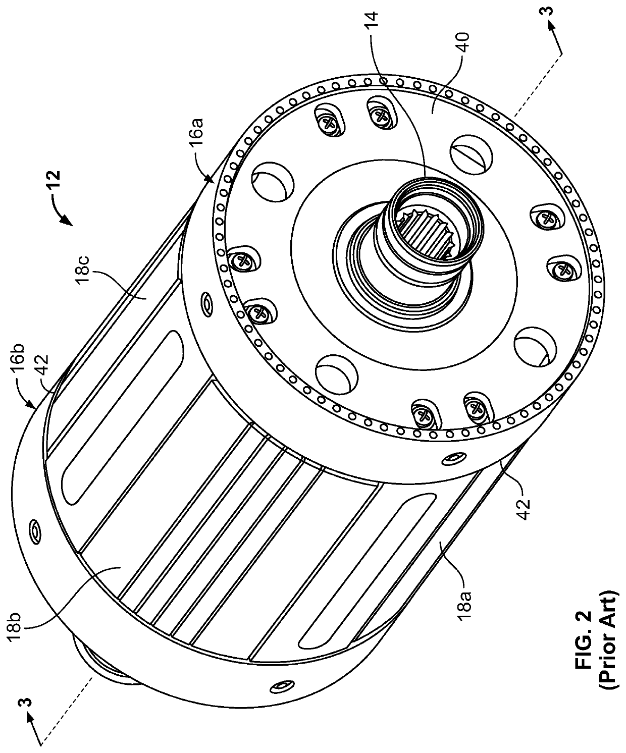
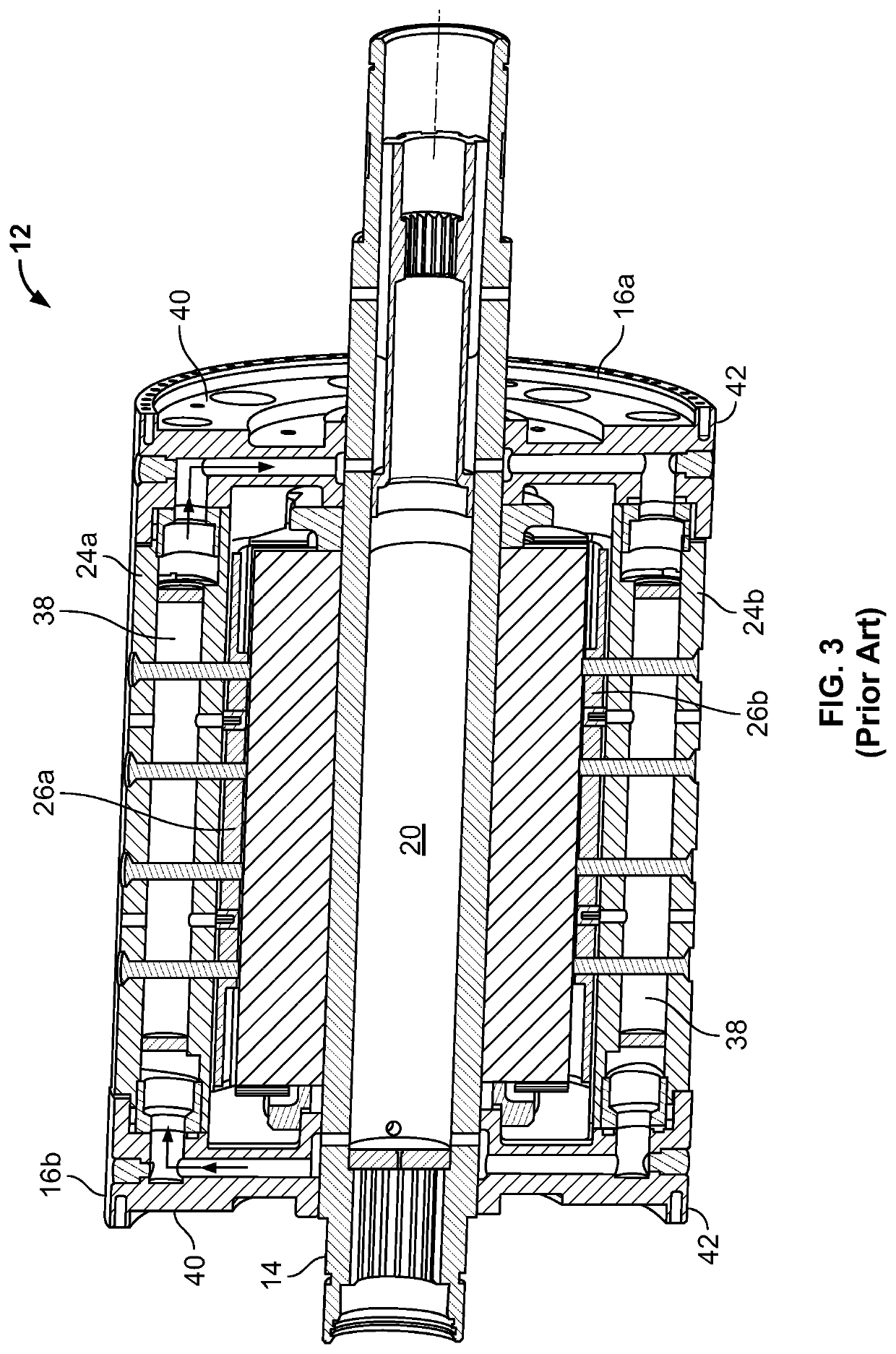
[0038]As such, described herein are embodiments of improved support wedge structures that provide stability and conductive cooling within rotor assembly of electrical generators, and processes for manufacturing the same. The inventive support wedge structures have cooling channel configurations that are conformal to the side walls of the support wedge structures that allow for increased conductive cooling as compared with conventional axial cooling channels. Beneficially, these cooling channel configurations may be manufactured using modern additive manufacturing techniques. The described embodiments allow for a more efficient operation of the electrical generators in which they are employed, as well as providing a longer service life.

Problems solved by technology

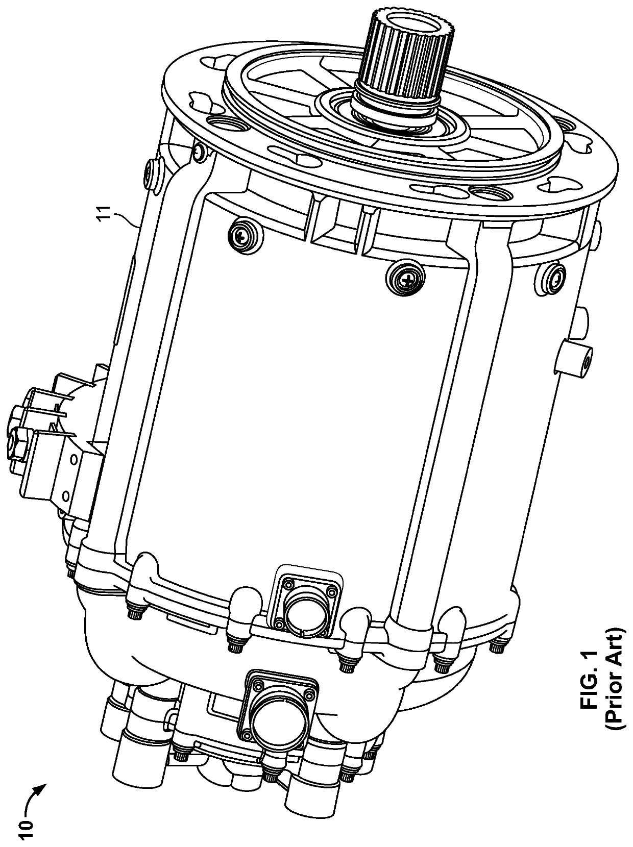
If an insufficient amount of heat is removed from the generator 10, then the power output from the generator 10 may be limited and the insulation of the wires within the generator 10 may degrade.
Conventional cooling systems such as air or limited conduction may, under certain circumstances, not offer sufficient heat dissipating capacity for high-speed generators.
This conventional tooling equipment is only capable of producing straight-line channels, and they cannot provide any curvature of less than 90 degrees.
Accordingly, the conductive cooling provided by these conventional cooling channels may not be optimum.
Sub-optimum cooling may result in problems such as limited power generating capacity and shorter component life.

Method used


Image

  • Conformal cooling devices for rotating generator elements and additive manufacturing processes for fabricating the same
  • Conformal cooling devices for rotating generator elements and additive manufacturing processes for fabricating the same
  • Conformal cooling devices for rotating generator elements and additive manufacturing processes for fabricating the same

Examples


Embodiment Construction

[0021]The following detailed description is merely exemplary in nature and is not intended to limit the invention or the application and uses of the invention. As used herein, the word “exemplary” means “serving as an example, instance, or illustration.” Thus, any embodiment described herein as “exemplary” is not necessarily to be construed as preferred or advantageous over other embodiments. All of the embodiments described herein are exemplary embodiments provided to enable persons skilled in the art to make or use the invention and not to limit the scope of the invention which is defined by the claims. Furthermore, there is no intention to be bound by any expressed or implied theory presented in the preceding technical field, background, brief summary, or the following detailed description.

[0022]Unless specifically stated or obvious from context, as used herein, the term “about” is understood as within a range of normal tolerance in the art, for example within 2 standard deviatio...


PUM


Abstract

Electrical generators having one or more conformal support and cooling devices for use in supporting and cooling rotating elements of the generator are disclosed herein. An electrical generator includes a housing, a shaft disposed axially through the housing, a rotor assembly including a plurality of poles that are disposed within the housing and mounted on the shaft, a support wedge disposed between two of the plurality of poles. The conformal support and cooling device includes an internal cooling channel in a helical configuration or a V-shape configuration that extends from a first length-wise end of the support and cooling device to a second length-wise end of the support and cooling device. Additive manufacturing processes are employed to fabricate the conformal support and cooling device.

Description

TECHNICAL FIELD[0001]The present disclosure is generally directed to devices for conductively cooling components of apparatuses that generate heat, and processes for manufacturing the same. More particularly, the present disclosure is directed to conformal cooling devices for use in cooling rotating electrical generator elements, and additive manufacturing processes for manufacturing the same. The disclosed cooling devices find application, for example, in aerospace components, such as power generation and conversion apparatuses of aircraft.BACKGROUND[0002]Electrical generators are used in many applications, including on gas turbine engines for aircraft, ships, and military vehicles. Such generators typically rotate at relatively high speeds (e.g., about 12,000 r.p.m. to about 24,000 r.p.m. or greater) during operation. Large centrifugal forces may be imposed upon the generator's rotating parts, such as the rotor. Generator rotors typically include a number of poles, each of which i...

Claims


Application Information

Patent Timeline
Patent Type & Authority Applications(United States)
IPC IPC(8): H02K5/20B33Y80/00H02K9/19H02K7/18H02K15/14F01B23/10
CPCH02K5/20B33Y80/00H02K9/19F05D2220/76H02K15/14F01B23/10F05D2220/32H02K7/1823H02K1/32H02K3/24H02K3/487
Inventor PHIELIX, TOMGODFREY, DONALDWALKER, EREKLOCKARD, REGINABIRDI, BALWINDERIYER, SHREYASWILSON, BENCOULAM, TODDBYRNES, SEANVAN OSTEN, KRISTEN
Owner HONEYWELL INT INC
Why Eureka
Try Eureka