
Electronic device including multiple printed circuit boards

Active Publication Date: 2021-12-02
SAMSUNG ELECTRONICS CO LTD
View PDF2 Cites 0 Cited by
  • Summary
  • Abstract
  • Description
  • Claims
  • Application Information

AI Technical Summary

Benefits of technology

This patent discusses a way to improve the design of printed circuit boards by integrating them with a connection member. This approach allows for easier removal of connectors, but can increase costs and decrease ease of repair. The patent also proposes a solution to secure a component arrangement area on printed circuit boards, which can further reduce costs and improve repair. Overall, this patent presents a solution to improve the design of printed circuit boards and reduce costs while maintaining ease of repair.

Problems solved by technology

An increase in size of the connector may reduce the design efficiency of the printed circuit board.
In the case of integrally configuring a printed circuit board and a connection member, the connector can be removed, but it may be disadvantageous in cost and the ease of repair may deteriorate.

Method used


Image

  • Electronic device including multiple printed circuit boards
  • Electronic device including multiple printed circuit boards
  • Electronic device including multiple printed circuit boards

Examples


Embodiment Construction

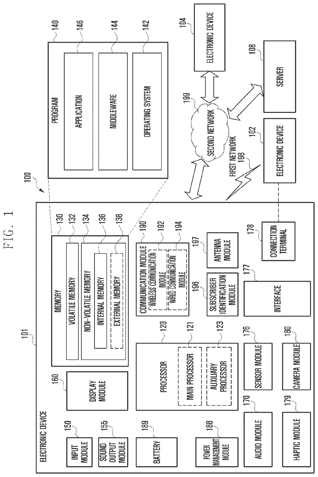
[0030]The following description with reference to the accompanying drawings is provided to assist in a comprehensive understanding of various embodiments of the disclosure as defined by the claims and their equivalents. It includes various specific details to assist in that understanding, but these are to be regarded as merely exemplary. Accordingly, those of ordinary skill in the art will recognize that various changes and modifications of the various embodiments described herein can be made without departing from the scope and spirit of the disclosure. In addition, descriptions of well-known functions and constructions may be omitted for clarity and conciseness.

[0031]The terms and words used in the following description and claims are not limited to the bibliographical meanings, but are merely used by the inventor to enable a clear and consistent understanding of the disclosure. Accordingly, it should be apparent to those skilled in the art that the following description of variou...


PUM


Abstract

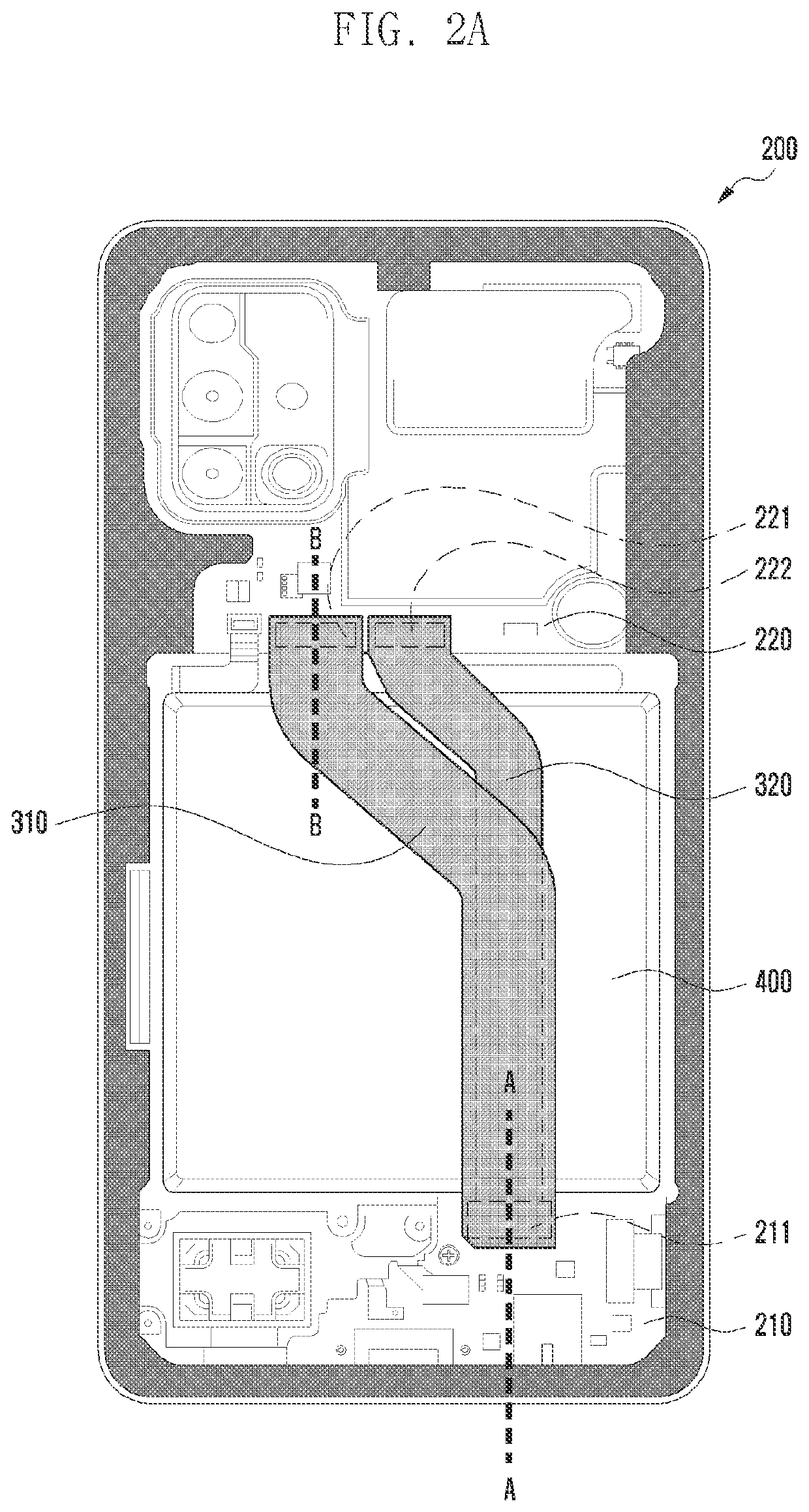
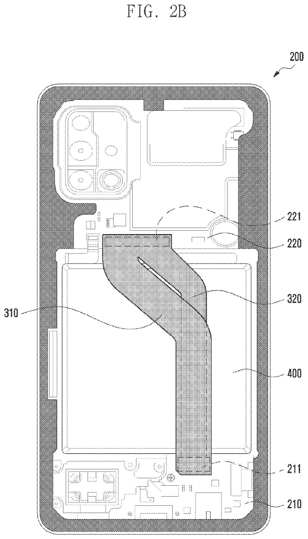
An electronic device is provided. The electronic device includes a first printed circuit board having a first surface and a second surface, a second printed circuit board having a first surface and a second surface disposed to be spaced apart from the first printed circuit board, a battery disposed between the first printed circuit board and the second printed circuit board, a first connection member to electrically connect the first printed circuit board and the second printed circuit board, and a second connection member to electrically connect the first printed circuit board and the second printed circuit board, wherein the first connection member and the second connection member may be arranged to at least partially overlap at a portion passing by the battery.

Description

CROSS-REFERENCE TO RELATED APPLICATION(S)[0001]This application is based on and claims priority under 35 U.S.C. § 119(a) of a Korean patent application number 10-2020-0066607, filed on Jun. 2, 2020, in the Korean Intellectual Property Office, the disclosure of which is incorporated by reference herein in its entirety.BACKGROUND1. Field[0002]The disclosure relates to an electronic device including a plurality of printed circuit boards.2. Description of Related Art[0003]Various electronic components constituting an electronic device are generally arranged on or connected to a printed circuit board (PCB).[0004]To configure an electronic device that can perform various functions, more types of electronic components are included in the electronic device. In addition, to increase the usage hours of a mobile electronic device, it is necessary to mount a large-capacity battery.[0005]In this situation, the area of a printed circuit board that can be installed in the limited internal space of...

Claims


Application Information

Patent Timeline
IPC IPC(8): H05K1/14H05K1/02H01M50/284
CPCH05K1/14H01M50/284H05K1/0201H05K1/0218H05K1/147H05K2201/10037H05K2201/052H05K2201/10189H05K1/0216H04M1/0277H04M1/0274H04M1/0262Y02E60/10H05K1/145
Inventor JU, WANJAEKIM, JAEHANLEE, SEUNGHAKYUN, JUNGYONGHWANG, SUNGCHEL
Owner SAMSUNG ELECTRONICS CO LTD
Learn More