Vacuum cleaner having tube and hose

a vacuum cleaner and tube technology, applied in the direction of pipes, cleaning equipment, mechanical equipment, etc., to achieve the effect of increasing the diameter, increasing the cross-section, and no negative impact on the resistan

Pending Publication Date: 2021-12-09
VERSUNI HLDG BV
View PDF0 Cites 0 Cited by
  • Summary
  • Abstract
  • Description
  • Claims
  • Application Information

AI Technical Summary

Benefits of technology

[0010]An embodiment of this invention provides a solution on how to design a flow-efficient diffusing bend, by using an oval cross section: provide an increased diameter in a first direction (a radial direction of the curve) and (substantially) not in a second direction perpendicular to the first direction. As the flow will separate in the upper and lower corner of the bend, increasing the cross-section there will have no negative impact on the resistance. Increasing the cross-section there will give more space for the air to ‘turn the corner’. Therefore, the flow will experience the diffusing tube in this direction as a less ‘steep’ corner and therefore giving a lower resistance. Because of (substantially) not increasing the bend in the sideway (perpendicular to the radial direction, the width of the bend when viewed in the radial direction of the curve) direction, the flow will not separate on the sides of the corner. This will lead to a lower total resistance of the bend while diffusing to a bigger diameter. As a result of manufacturing constraints, the dimension in the second direction may not be entirely constant.

Problems solved by technology

Due to the small diameter in combination with the ribbed-structure the resistance of the hose is very high and a main contributor to the losses in the current vacuum cleaners.

Method used


Image

  • Vacuum cleaner having tube and hose

Examples


Embodiment Construction

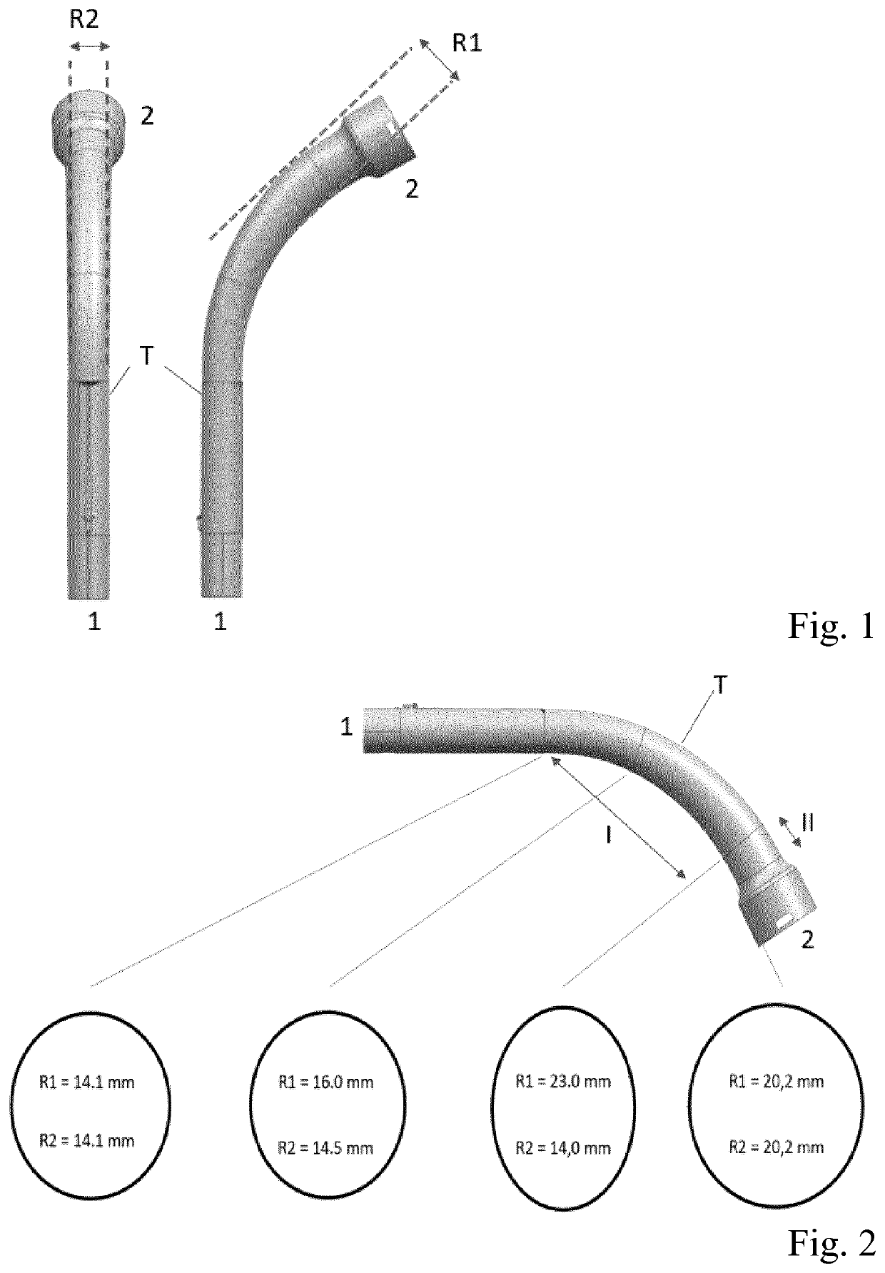
[0013]FIGS. 1 and 2 shows a transition piece according to an embodiment of the invention, which will be positioned between a tube and a hose of a vacuum cleaner.

[0014]FIG. 1 shows two views of the transition piece. The left view shows that the dimension R2 is substantially constant, while the right-hand view shows that the dimension R1 increases from a first end of the transition piece that is to be connected to the tube of the vacuum cleaner towards a second end of the transition piece that is to be connected to a hose of the vacuum cleaner. Herein, R1 is in a radial direction of a curved part of the transition piece, while R2 is in a direction perpendicular to R1.

[0015]FIG. 2 illustrates example values of R1 and R2 at several places of the transition piece, for use with a tube that has a diameter of about 14 mm and a hose that has a diameter of about 20 mm. In the example shown, it is clear that during the curve R1 increases, while R2 remains substantially constant ate about 14 mm...


PUM


Abstract

Vacuum cleaner, comprising a tube having a first diameter, a hose having a second diameter exceeding the first diameter by at least 15%, and a transition piece (T) having a first end (1) arranged for being connected to the tube, and a second end (2) arranged for being connected to the hose, wherein the transition piece (T) has a curved part that has a non- circular cross-section, the curved part having a first part (I) in which in a direction from the first end (1) to the second end (2), a first dimension (R1) of the cross-section increases to a diameter exceeding the first diameter by 15%, the first dimension (R1) being in a radial direction of the curved part, while a second dimension (R2) of the cross-section, perpendicular to the first dimension (R1), does not exceed the first diameter by more than 10%. Preferably, the transition piece (T) has a second part (II), between the first part (I) and the second end (2), the second part (II) having a non-circular cross-section where the second part (II) meets the first part (I), and a circular cross-section where the second part meets the second end (2). Advantageously, in the first part (I), in a direction from the first end (1) to the second end (2), the first dimension (R1) of the cross-section increases to a diameter exceeding the second diameter, while the second dimension (R2) stays below the second diameter.

Description

FIELD OF THE INVENTION[0001]The invention relates to a vacuum cleaner having a tube and a hose.BACKGROUND OF THE INVENTION[0002]Current vacuum cleaner components have been developed in times that 2100 W input power could be used to drive a vacuum cleaner. Due to the huge amount of (air) power there was no need to develop components with a focus on low-resistance to airflow.[0003]Currently, vacuum cleaners are being re-developed to work at low input power levels even down to 300 W, i.e. about 1 / 7 of original input power level. This means all components need to be optimized to have a resistance and an airflow leakage that are as low as possible to achieve the highest possible suction power at the nozzle.[0004]US20170007085 discloses a vacuuming apparatus, wherein a hollow wand handle includes a first circumferential surface portion having a first outer diameter and a second circumferential surface portion having a second outer diameter that is larger than the first outer diameter.SUMM...

Claims


Application Information

Patent Timeline
Patent Type & Authority Applications(United States)
IPC IPC(8): A47L9/24
CPCA47L9/242A47L9/248A47L9/24F16L9/006Y10S138/11
Inventor VAN DER KOOI, JOHANNES TSEARDELZINGA, MARKKLEINE-DOEPKE, BASTIAN CORNELIS
Owner VERSUNI HLDG BV
Why Eureka
Try Eureka