
Dental implant system
- Summary
- Abstract
- Description
- Claims
- Application Information
AI Technical Summary
Benefits of technology
Problems solved by technology
Method used
Image

Examples
Embodiment Construction
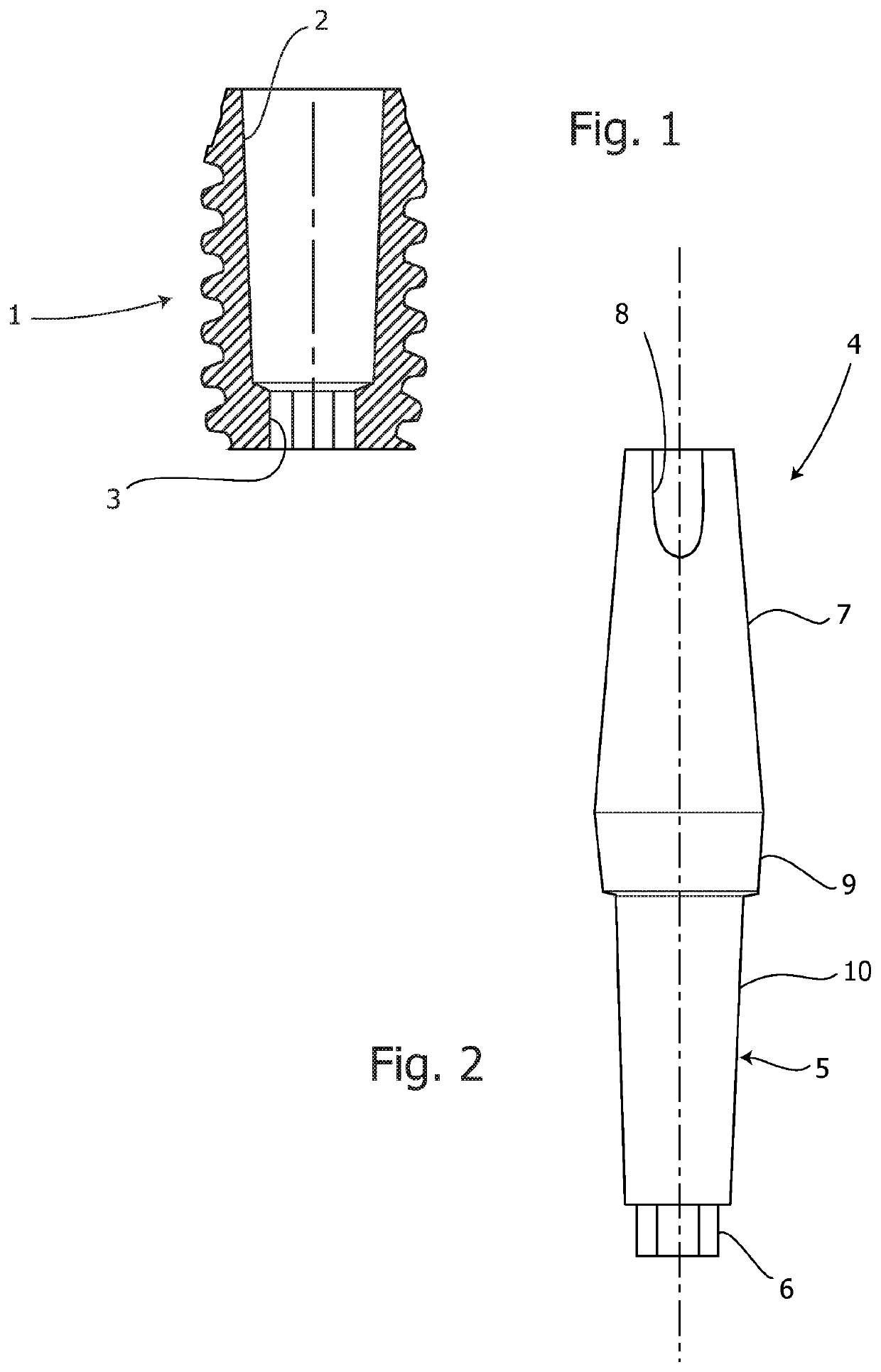
[0029]Reference is initially made to FIG. 1 which is a central longitudinal section of a dental implant according to the present invention. The dental implant, which is indicated generally as 1, is represented as of the screw type, but in the following it is shown that it could also be different, such as of a plateau type. Designated as 2 is a frustoconical cavity which is a longitudinal through hole for the insertion of an abutment complete with a dental crown. The frustoconical cavity 2 has, on a side opposite to the insertion side of the abutment, that is to say in its base or apical end, a non-round end space 3, for example of hexagonal prismatic shape. Thanks to the fact that the frustoconical cavity 2 is a longitudinal through hole, the dimensions of the implant 1 are reduced, even by 0.3-2 mm, compared to a conventional implant without a through cavity.
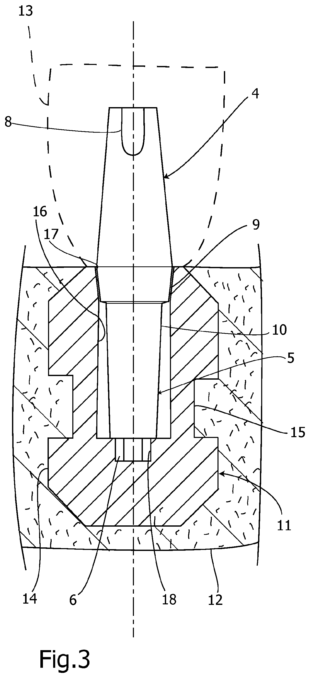
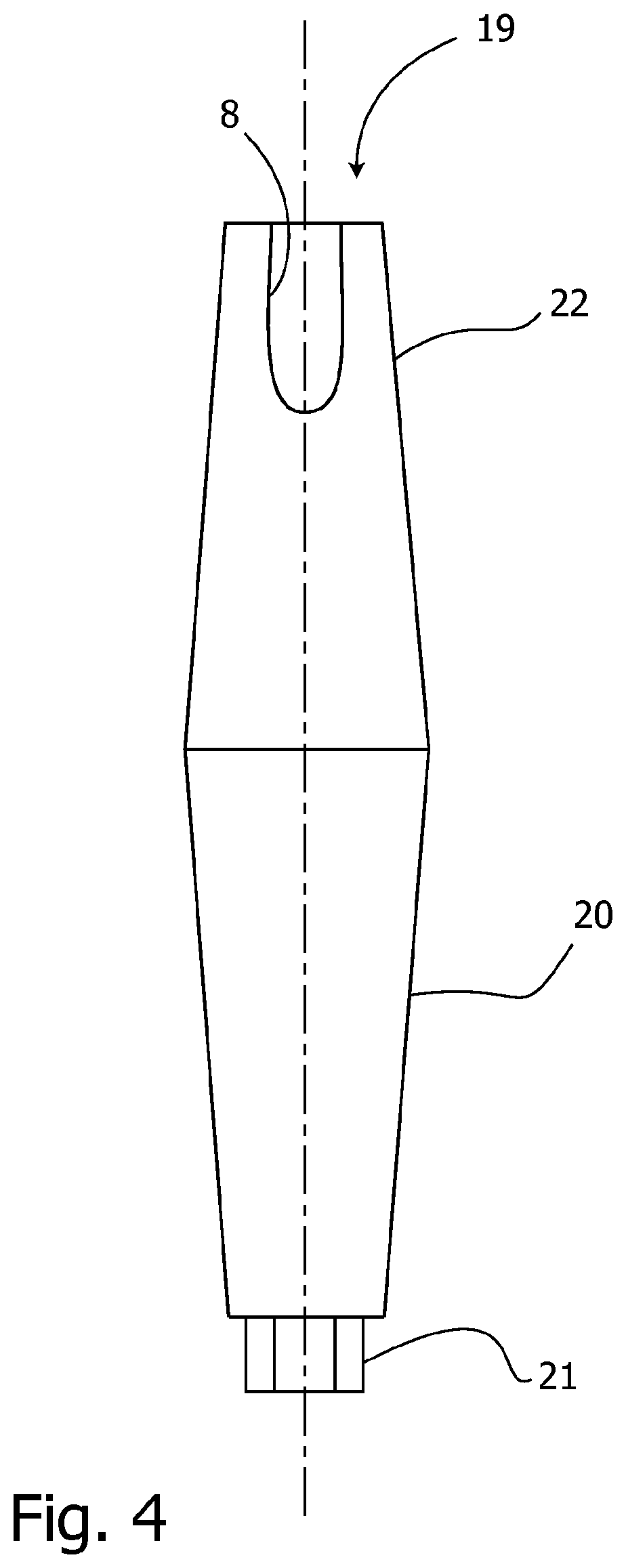
[0030]FIG. 2 is a schematic side view of a transfer according to the present invention. Traditionally, the transfer, indicate...
PUM
 Abstract
Description
Claims
Application Information