Semiconductor device having metallic lead and electronic device having lead frame
- Summary
- Abstract
- Description
- Claims
- Application Information
AI Technical Summary
Benefits of technology
Problems solved by technology
Method used
Image
Examples
first embodiment
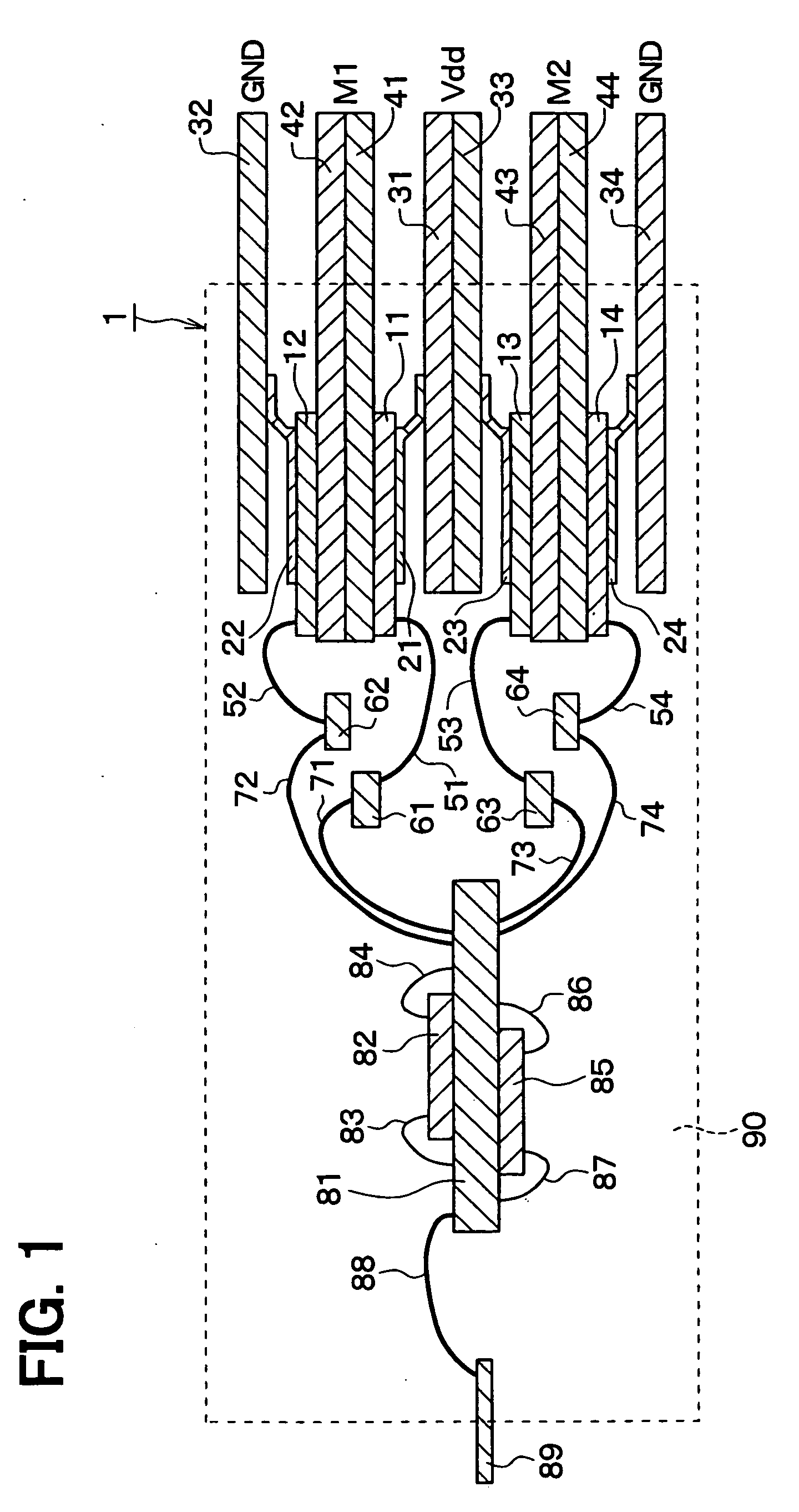
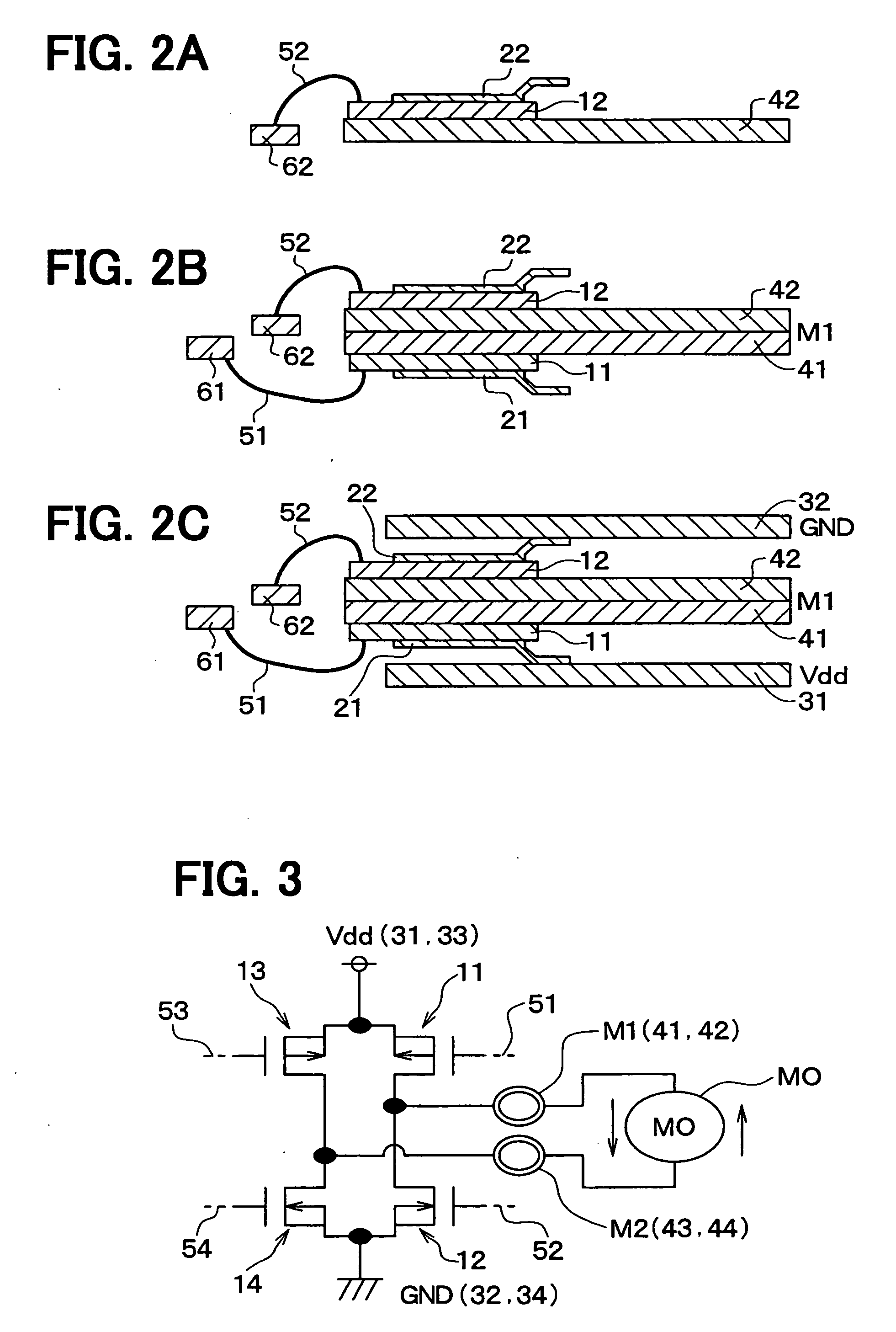
[0062] Referring now to drawings, a first embodiment of the present invention will be described. A semiconductor device indicated in this first embodiment is applied to an HIC (Hybrid Integrated Circuit) which drives a driving motor of a power window.
[0063]FIG. 1 is a sectional view for schematically showing a semiconductor device 1 according to the first embodiment of the present invention. As shown in this drawing, the semiconductor device 1 has been equipped with a first semiconductor element 11 to a fourth semiconductor element 14. Each of the first to fourth semiconductor elements 11 to 14 has a rectangular shape, and has been made by that a power element having a MOS structure is formed on a semiconductor substrate, for example, a silicon semiconductor, while a heat generation amount of the power element is large.
[0064] Concretely speaking, P-ch (P channel) type DMOS elements have been formed in the first and third semiconductor elements 11 and 13, and N-ch (N channel) type ...
second embodiment
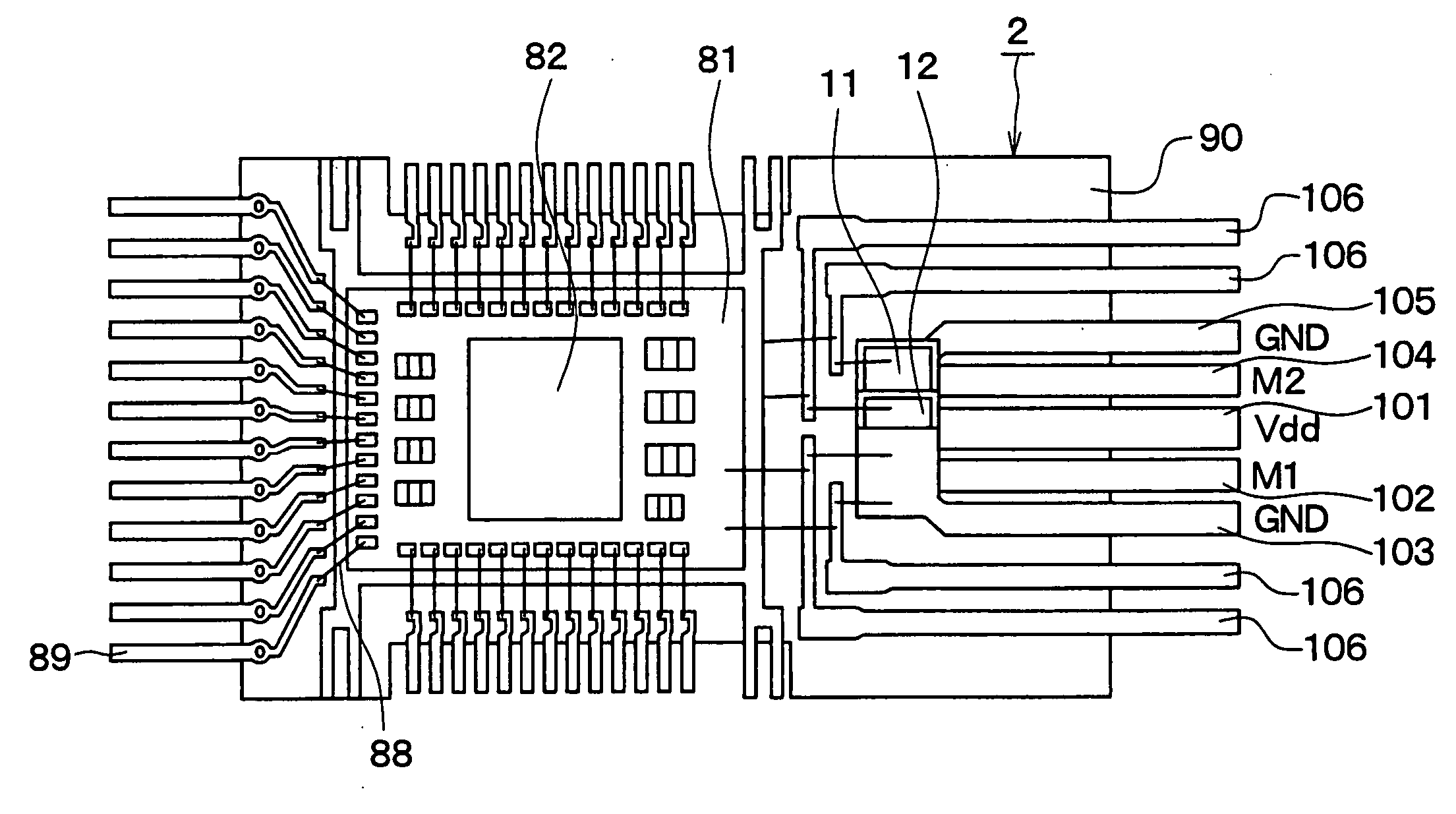
[0110] In a second embodiment of the present invention, only different portion from that of the first embodiment will be explained. That is, in this second embodiment, such an arrangement is different from that of the first embodiment, namely, respective leads 31 to 34, 41 to 44, and 89 are arranged in an in-line type on the same plane.
[0111]FIG. 4A and FIG. 4B are diagrams for indicating a semiconductor device 2 according to this second embodiment. That is, FIG. 4A is a plan view for indicating the semiconductor device 2, and FIG. 4B is a sectional view for schematically indicating the semiconductor device 2. Also, FIG. 5 schematically represents an arrangement of the respective semiconductor elements 11 to 14 in FIG. 4A. It should be noted that in FIG. 5, the respective leads 101 to 106 are omitted. Also, in FIG. 4B, an outer wall portion of the resin 90 is indicated by a broken line, and the resin 90 has been filled inside the broken line.
[0112] As indicated in FIG. 4A, in this...
third embodiment
[0121] In a third embodiment of the present invention, only different portion from that of the above-explained embodiments will be explained. That is, in this third embodiment, such an arrangement is different from that of the above-described embodiments, namely, shapes of respective leads functioning as a Vdd terminal and a GND terminal, which are joined to the respective semiconductor elements 11 to 14, are different from those of the first and second embodiments.
[0122]FIG. 6 is a sectional view for schematically showing a semiconductor device 3 according to this third embodiment. FIG. 7 is a view for indicating the semiconductor device 3, as viewed along an arrow “VII” of FIG. 6. It should be noted that an outer wall portion of the resin 90 is indicated by a broke line, and the resin 90 has been filled inside the broken line in FIG. 6. Also, in FIG. 7, since ribbon leads 22 and 24, M1 and M2 terminals (leads 41 to 44), and a Vdd terminal (lead 112) are omitted, only a lead 111 f...
PUM
 Abstract
Description
Claims
Application Information
 - R&D
- Intellectual Property
- Life Sciences
- Materials
- Tech Scout
- Unparalleled Data Quality
- Higher Quality Content
- 60% Fewer Hallucinations
Browse by: Latest US Patents, China's latest patents, Technical Efficacy Thesaurus, Application Domain, Technology Topic, Popular Technical Reports.
© 2025 PatSnap. All rights reserved.Legal|Privacy policy|Modern Slavery Act Transparency Statement|Sitemap|About US| Contact US: help@patsnap.com


