Method for labeling image

a labeling and image technology, applied in the field of image processing, can solve the problems of large image data, inability to collect and label computer surface images with sufficient diversity, and insufficient infrastructure for collecting big data, etc., and achieve the effect of reducing false negative determinations and effectively reducing false positives

Active Publication Date: 2021-12-09
INVENTEC PUDONG TECH CORPOARTION +1
View PDF0 Cites 0 Cited by
  • Summary
  • Abstract
  • Description
  • Claims
  • Application Information

AI Technical Summary

Benefits of technology

[0008]In sum, the present disclosure proposes a method for labeling image works for both classification and detection in respect to the original image of the computer products. The present disclosure reduces the need of a large amount of (human-)labeled image data for training purposes. The present disclosure is not over-generalized so that it treats some defects as the texture pattern in normal regions. Therefore, the present disclosure reduces the false negative determinations (failing to spot abnormal samples or regions). The present disclosure mimics human perception by highlighting only anomaly while ignoring complex background, such perceptual-attention based method reduces false positives effectively.

Problems solved by technology

However, training image collection and labeling require a lot of labors and can be hard due to several reasons.
For example, manufacturing facilities where the computers are manufactured, are not equipped with infrastructure in collecting big data, especially large amount of image data.
If such data collection and labeling tasks are outsourced, security, integrity, and confidentiality of the data can cause a great concern.
More importantly, as computer life cycles become shorter and product designs become more diverse, it becomes impractical to collect and label computer surface images with sufficient diversity.
In addition, there are many types of surface defects such as scratch, dent, smudge, etc.
To make matters worse, some surface defects cannot be easily categorized.
There will be inevitably inconsistent labels in the training data.
Therefore, it's hard to collect a large amount of consistent labeled data with sufficient varieties.

Method used


Image

  • Method for labeling image
  • Method for labeling image
  • Method for labeling image

Examples


Embodiment Construction

[0022]In the following detailed description, for purposes of explanation, numerous specific details are set forth in order to provide a thorough understanding of the disclosed embodiments. It will be apparent, however, that one or more embodiments may be practiced without these specific details. In other instances, well-known structures and devices are schematically shown in order to simplify the drawings.

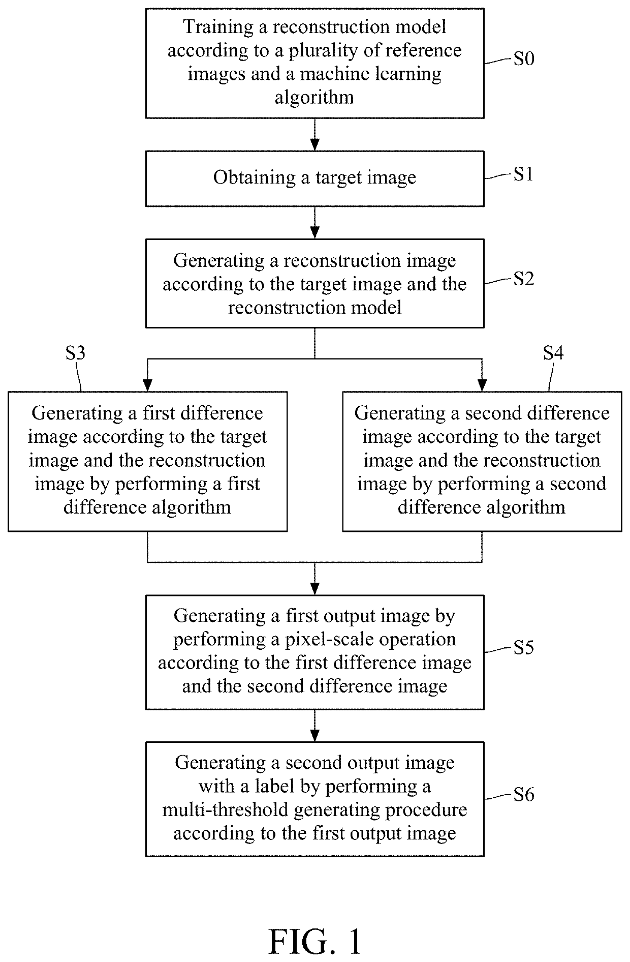
[0023]A method for labeling image proposed by the present disclosure is suitable to detect a defect of a target object, and generate a supplementary labels associated with the defect in a target images having the target object. For an example, the target object is a surface of a computer product, such as a top cover of a laptop, and the defect is a scratch, a dent, a smudge, or the like on the top cover. For another example, the target object is a printed circuit board (PCB), and the defect is a missing component, a skew component, or a wrong component.

[0024]Please refer to FIG. 1,...


PUM


Abstract

A method for labeling image comprises: obtaining a target image of a target object; generating a reconstruction image according to the target image and a reconstruction model, wherein the reconstruction model is trained with a plurality of reference images and a machine learning algorithm, each of the reference images is an image of a reference object whose defect level is in a tolerable range with an upper limit, and each of the reference objects is associated with the target object; generating a first difference image and a second difference image respectively by performing a first difference algorithm and a second difference algorithm respectively according to the target image and the reconstruction image; and generating an output image by performing a pixel-scale operation according to the first difference image and the second difference image, wherein the output image includes a label indicating a defect of the target object.

Description

CROSS-REFERENCE TO RELATED APPLICATIONS[0001]This non-provisional application claims priority under 35 U.S.C. § 119(a) on Patent Application No(s). 202010507192 filed in China on Jun. 5, 2020, the entire contents of which are hereby incorporated by reference.1. Technical Field[0002]This disclosure relates to the field of image processing, and more particularly to a method for labeling a defect of an object in an image.2. Related Art[0003]Computers, such as laptops, tablets and the likes, need to be inspected and confirmed by quality control personnel before their final shipment to the customers. Such quality control personnel will check for scratches, dents, and other surface defects specified in an inspection-guideline documentation. If the severity of the surface defects is beyond what are allowed in the specification, the computer is then considered “failed”, as opposite to “pass” in the surface defect detection test.[0004]To detect computer appearance imperfections, it is possib...

Claims


Application Information

Patent Timeline
Patent Type & Authority Applications(United States)
IPC IPC(8): G06K9/62
CPCG06K9/6256G06K2209/21G06K9/6262G06K9/6232G06T7/0004G06T7/40G06T7/49G06T2207/30204G06T2207/20081G06T2207/30108G06T2207/20084G06F18/22G06F18/24G06V10/993G06V10/82G06V10/764G06V2201/07G06F18/214G06F18/213G06F18/217
Inventor CHEN, YI-CHUNCHEN, TRISTA PEI-CHUNTAN, DANIEL STANLEY YOUNGCHEN, WEI-CHAO
Owner INVENTEC PUDONG TECH CORPOARTION
Why Eureka
Try Eureka