
Method and Device for Determining the Degradation of a Battery Module or Battery Cell

a battery module and degradation technology, applied in the direction of measurement devices, electrical testing, instruments, etc., can solve the problems of battery health management becoming a more significant issue, affecting the accuracy and reliability of machine learning models, and affecting the accuracy of battery health managemen

Pending Publication Date: 2022-07-21
SIEMENS AG
View PDF0 Cites 0 Cited by
  • Summary
  • Abstract
  • Description
  • Claims
  • Application Information

AI Technical Summary

Benefits of technology

The invention allows for easy and cost-efficient way to determine the degradation of a battery module without the need for manual interaction. This is done through in-situ-measurements, which can be done without a laboratory testing environment. The determined degradation can be used to better control the battery module, leading to reduced downtime and cost for the system. The invention also uses a d / q transformation to accurately describe the load being powered by the battery module and can easily capture the voltage or current through sensors. The environmental parameter set can also include ambient air temperature to further aid in calculating the degradation. Additionally, statistical data and machine learning models can be used to calculate the degradation based on the battery usage in controlled conditions. These methods make it simple and reliable to determine the degradation of a battery module.

Problems solved by technology

The problem of battery health management is now becoming a more significant issue as electric mobility and large-scale battery systems for grid level energy storage become increasingly prevalent.
The nature of these large systems typically renders measurement of current levels of health difficult and costly.
However, the machine learning model still lacks accuracy and reliability of the prediction for certain applications.

Method used


Image

  • Method and Device for Determining the Degradation of a Battery Module or Battery Cell
  • Method and Device for Determining the Degradation of a Battery Module or Battery Cell

Examples


Embodiment Construction

[0052]It is clear, that further not shown parts are necessary for the operation of a device, e.g., sensor devices, driver circuitries, electric connection to a power supply and electronic control components but also mechanical parts, like housings or fastening materials. For the sake of better understanding these parts are not illustrated and described.

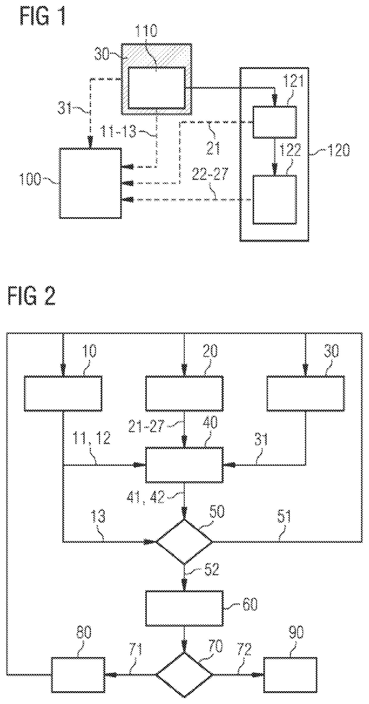
[0053]FIG. 1 shows a schematic illustration of an embodiment of a device in accordance with the invention with a battery monitoring device 100 with a calculation unit and a memory for determining the degradation of a battery module 110 or a battery cell.

[0054]The battery module 110 is configured to deliver energy to an electric load 120.

[0055]The electric load comprises an inverter 121 and an electric motor 122, where the inverter 121 controls and supplies the motor 122.

[0056]The battery monitoring device 100 is configured to capture a battery parameter set 10 including a battery module / cell temperature 11, a battery module / cell volta...


PUM

PropertyMeasurementUnit
angleaaaaaaaaaa
energyaaaaaaaaaa
temperatureaaaaaaaaaa

Abstract

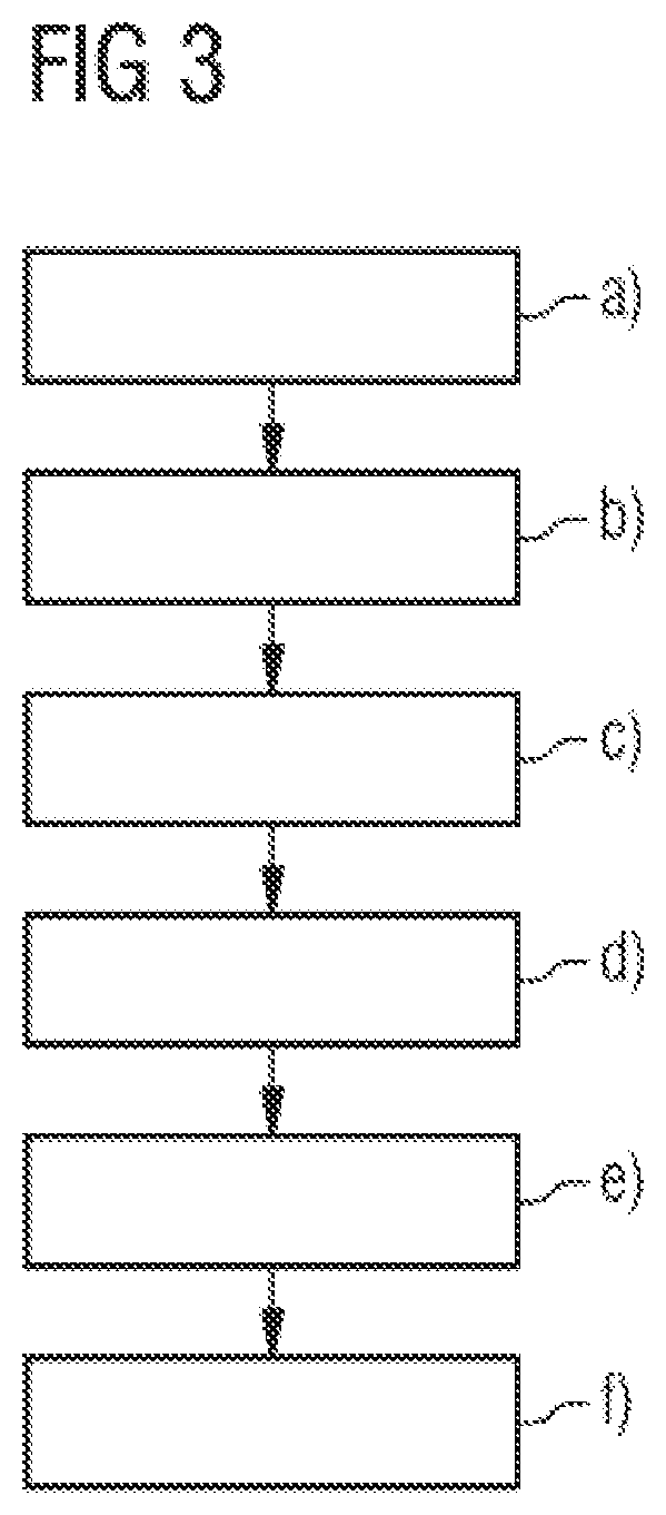
Method for determining the degradation of a battery module or a battery cell that each deliver energy to an electric load, wherein a) a battery parameter set comprising an actual temperature of the battery module is captured, b) a load parameter set is captured, c) an environmental parameter set is captured, d) a machine learning model is set up and trained with the battery parameter set, the load parameter set and the environmental parameter set, e) a predicted temperature and a standard deviation thereof is calculated using the machine learning model, and the degradation of the battery module is determined using a predicted temperature, the standard deviation and the actual temperature, where a change over the time of the probability of measuring the actual module or cell temperature, which is normal distributed, is an indicator for the degradation of the battery module or battery cell.

Description

CROSS-REFERENCE TO RELATED APPLICATIONS[0001]This is a U.S. national stage of application No. PCT / EP2020 / 063965 filed 19 May 2020. Priority is claimed on European Application No. 19176730.0 filed 27 May 2019, the content of which is incorporated herein by reference in its entirety.BACKGROUND OF THE INVENTION1. Field of the Invention[0002]The invention relates to a method and a device for determining the degradation of a battery module or battery cell.2. Description of the Related Art[0003]The problem of battery health management is now becoming a more significant issue as electric mobility and large-scale battery systems for grid level energy storage become increasingly prevalent. The nature of these large systems typically renders measurement of current levels of health difficult and costly.[0004]The health of a battery indicates in-depth details about battery aging effects such as the remaining absolute usage time, where the aging effects are caused, for instance, by the number of...

Claims


Application Information

Patent Timeline
Patent Type & Authority Applications(United States)
IPC IPC(8): G01R31/367G01R31/392H01M10/48
CPCG01R31/367H01M10/486G01R31/392G01R31/374Y02E60/10
Inventor FENECH, KRISTIANBALAZS, GERGELY GYÖRGYFISCHER, HANNA
Owner SIEMENS AG
Learn More