Exhaust purification device for internal combustion engine

a purification device and exhaust technology, applied in the direction of machines/engines, mechanical equipment, separation processes, etc., can solve the problems of reducing becoming difficult to accurately detect the pm amount, etc., to reduce the determination of the filter trouble, the detection accuracy of the pm sensor can be restricted, and the effect of reducing the determination of the troubl

Active Publication Date: 2015-11-10
TOYOTA JIDOSHA KK
View PDF13 Cites 0 Cited by
  • Summary
  • Abstract
  • Description
  • Claims
  • Application Information

AI Technical Summary

Benefits of technology

[0036]According to the present invention, the decrease in the determination on the filter trouble due to the decrease in the detection accuracy of the PM sensor can be restricted.

Problems solved by technology

It may become difficult to accurately detect the PM amount when the intermediate products attach to an electrode or a cover of the PM sensor.
This may decrease accuracy of a determination on filter trouble.

Method used


Image

  • Exhaust purification device for internal combustion engine
  • Exhaust purification device for internal combustion engine
  • Exhaust purification device for internal combustion engine

Examples


first embodiment

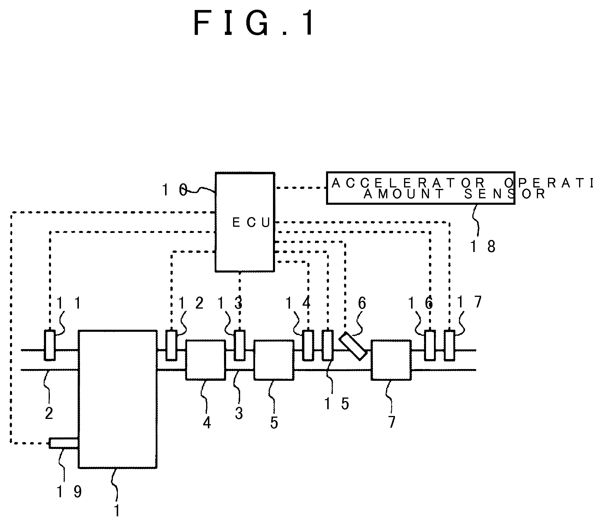
[0052]FIG. 1 illustrates a schematic configuration of the exhaust purification device for an internal combustion engine in accordance with this embodiment. An internal combustion engine 1 shown in FIG. 1 is a diesel engine but may be a gasoline engine.

[0053]An intake passage 2 and an exhaust passage 3 are connected to the internal combustion engine 1. An air flow meter 11 that detects an amount of intake air flowing through the intake passage 2 is provided in the intake passage 2. Meanwhile, an oxidation catalyst 4, a filter 5, an injection valve 6, and a selective reduction type NOx catalyst 7 (referred to as NOx catalyst 7 hereinafter) are provided from an upstream side in a direction of exhaust flow.

[0054]The oxidation catalyst 4 may be a catalyst that has oxidation ability, for example, a three-way catalyst. The oxidation catalyst 4 may be carried on the filter 5.

[0055]The filter 5 collects PM in the exhaust. A catalyst may be carried on the filter 5. The filter 5 collects the P...

second embodiment

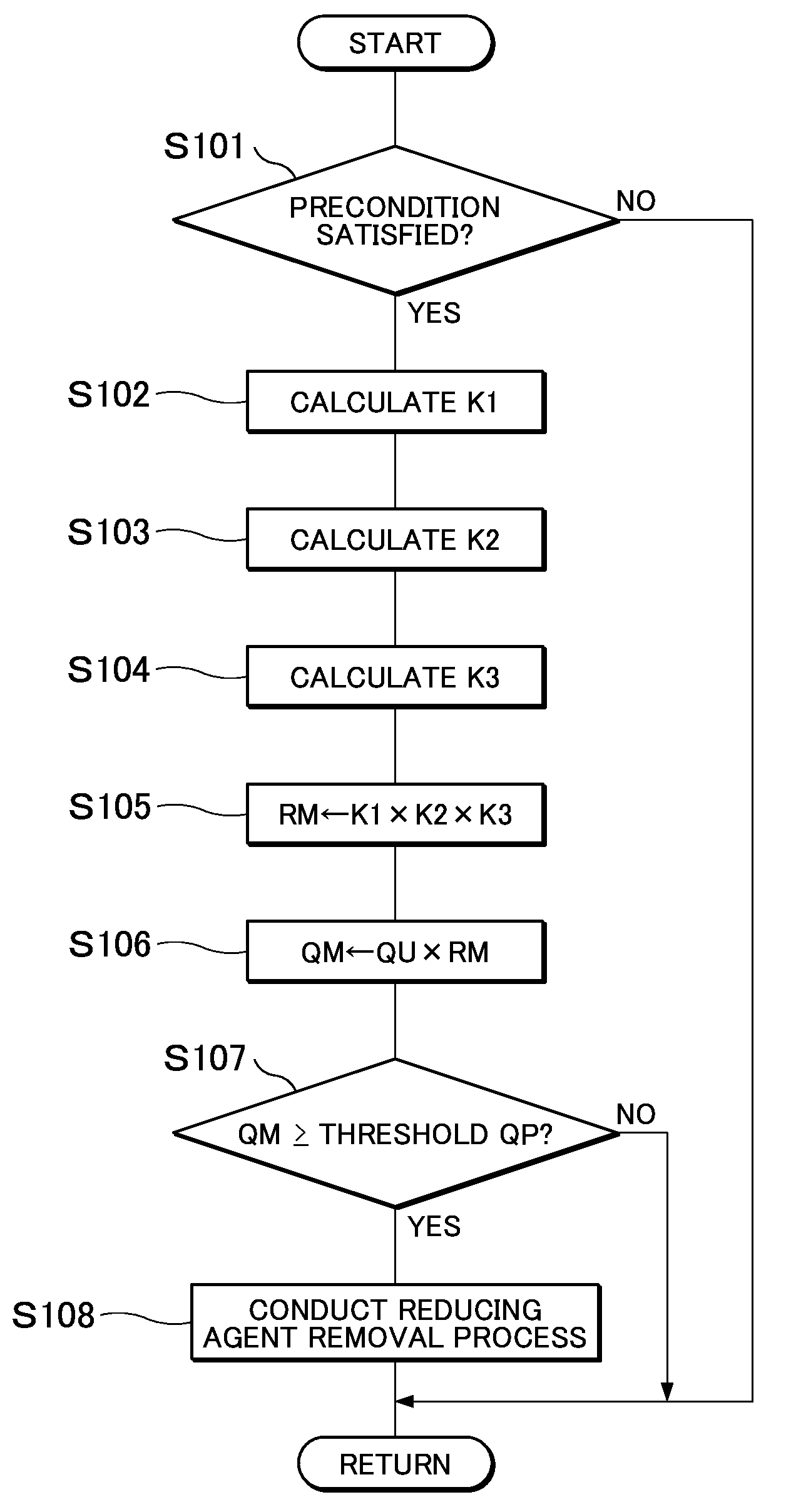
[0106]In the flow shown in FIG. 6, the reducing agent removal process is conducted when the estimation production amount QM is equal to or larger than the threshold. It can also be considered that the reducing agent removal process is conducted when the reducing agent amount that passes through the NOx catalyst 7 exceeds an allowable range. In contrast, in this embodiment, the reducing agent removal process is conducted in a case where the reducing agent passes through the NOx catalyst 7 independently from the amount of the reducing agent that passes through the NOx catalyst 7. For example, the reducing agent removal process is conducted in a case where at least one of the following conditions is satisfied that the flow rate or the flow speed of the exhaust that passes through the NOx catalyst 7 is equal to or higher than the threshold, that the temperature of the NOx catalyst or the temperature of the exhaust is equal to or lower than the threshold, and that the adsorption rate of ...

third embodiment

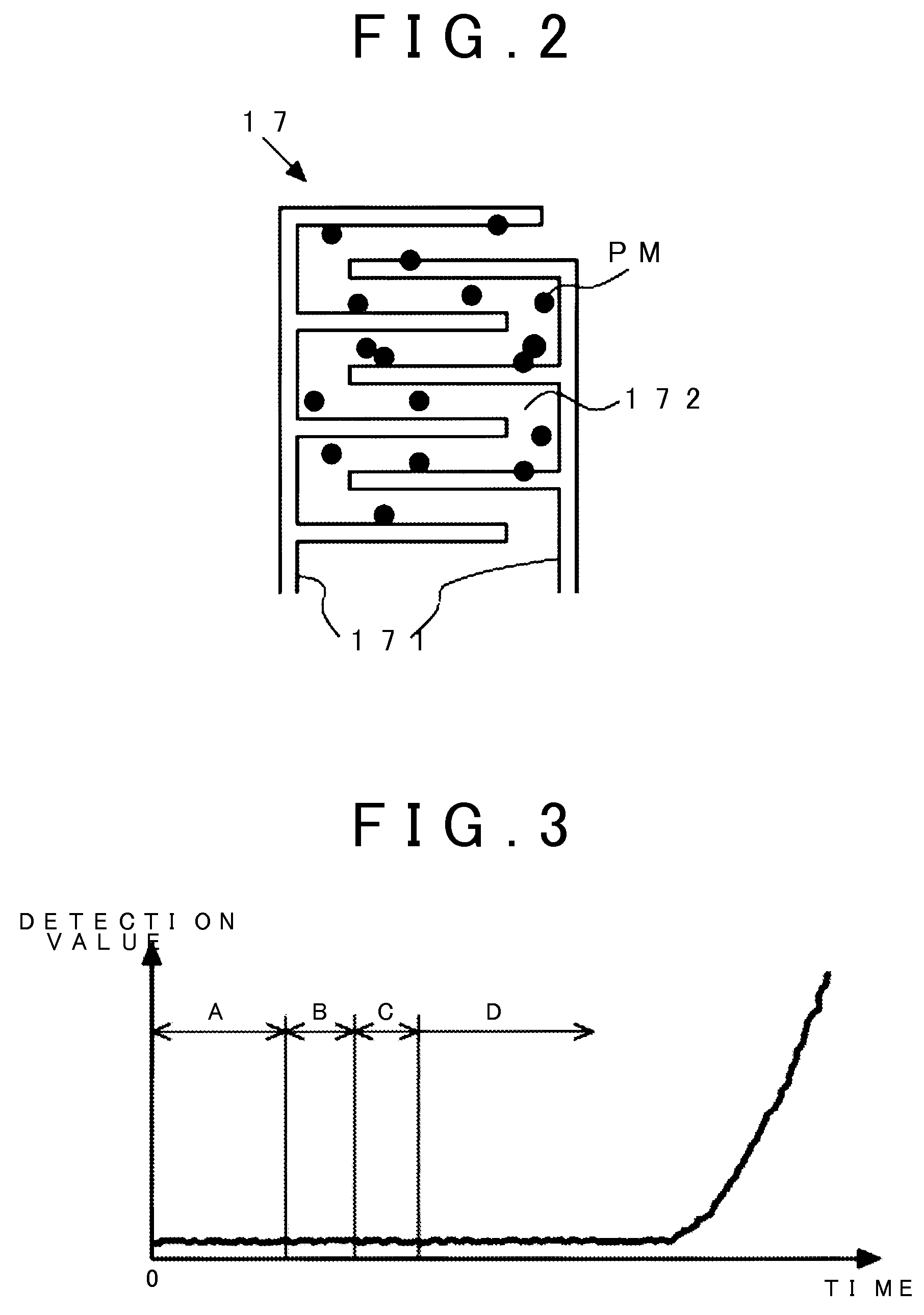
[0113]In this embodiment, a decrease in the detection value of the PM sensor 17 is added to conditions for conducting the reducing agent removal process other than the conditions described in the first and second embodiments. Other devices and the like are the same as the first embodiment, and the description will not be repeated.

[0114]Here, as shown in FIG. 5, if the PM sensor 17 is normal, the detection value increases along with the lapse of time or the detection value does not change unless the reducing agent removal process or a PM removal process is conducted. In other words, if the PM sensor 17 is normal, the detection value does not decrease along with the lapse of time. On the other hand, when the reducing agent attaches to the PM sensor 17, the detection value may decrease due to vaporization of the reducing agent.

[0115]Thus, a determination can be made that the reducing agent attaches to the PM sensor 17 in a case where the detection value of the PM sensor 17 decreases. F...


PUM

PropertyMeasurementUnit
temperatureaaaaaaaaaa

Abstract

A decrease in determination accuracy on filter trouble due to a decrease in detection accuracy of a PM sensor is restricted. A filter, a selective reduction type NOx catalyst provided on a downstream of the filter, the PM sensor detecting an amount of PM on a downstream of the selective reduction type NOx catalyst, and a removal section conducting a process for removing a reducing agent attached to the PM sensor in a case where at least one of conditions is satisfied that a temperature of the selective reduction type NOx catalyst is equal to or lower than a threshold, that a temperature of the exhaust is equal to or lower than a threshold, that a flow rate of the exhaust is equal to or higher than a threshold, and that an adsorption amount of the reducing agent in the selective reduction type NOx catalyst is equal to or larger than a threshold are included.

Description

TECHNICAL FIELD[0001]The present invention relates to an exhaust purification device for an internal combustion engine.BACKGROUND ART[0002]A technique (for example, see Patent Document 1) has been known that prohibits supply of an aqueous urea solution when an accumulation amount of intermediate products that are produced in a reaction from urea to ammonia in an exhaust passage reaches an upper limit amount in an exhaust purification device that supplies urea to a selective reduction type NOx catalyst (also simply referred to as “NOx catalyst” hereinafter). According to the technique, a reducing agent can be supplied to the NOx catalyst until the accumulation amount of the intermediate products in the exhaust passage reaches the upper limit amount.[0003]Incidentally, a filter for collecting particulate matters (also simply referred to “PM” hereinafter) may be installed in the exhaust passage. In addition, a PM sensor that detects a PM amount in the exhaust is installed for determina...

Claims


Application Information

Patent Timeline
Patent Type & Authority Patents(United States)
IPC IPC(8): B01D53/94F01N3/20F01N3/035
CPCB01D53/9495F01N3/035F01N3/2066B01D53/9409B01D2251/2067F01N2560/05F01N2610/02F01N2610/1493F01N2900/0408F01N2900/1404F01N2900/1411Y02T10/24Y02T10/12
Inventor SHIRASAWA, TAKERUOGISO, MAKOTONOGI, YOSHITO
Owner TOYOTA JIDOSHA KK
Why Eureka
Try Eureka