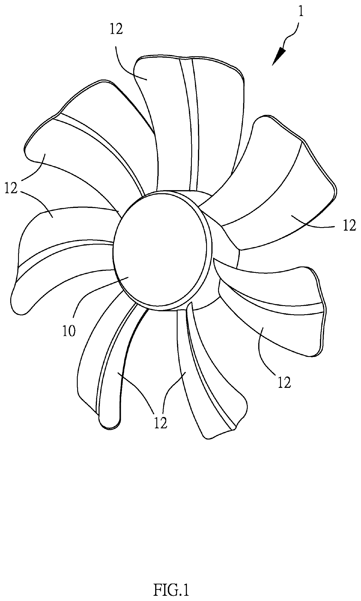
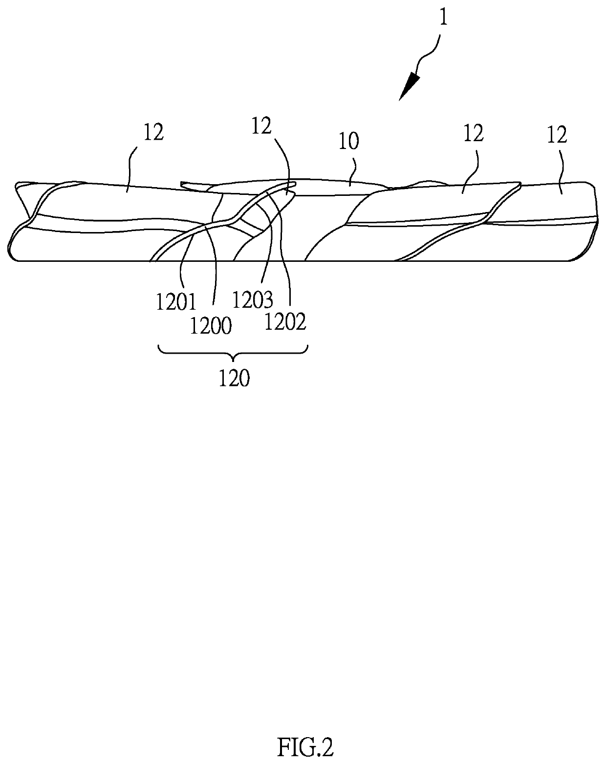
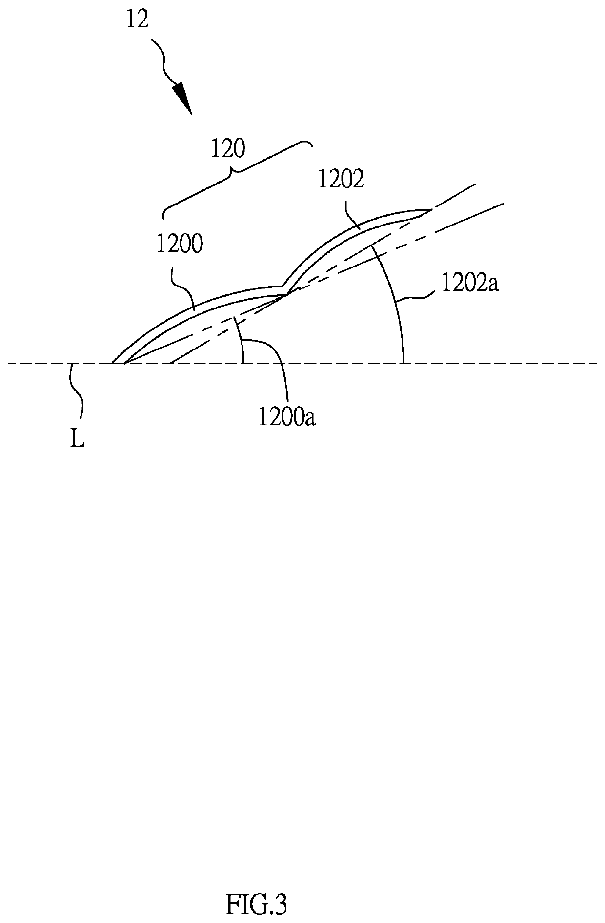
Fan blade structure

a technology of blade structure and fan blade, which is applied in the direction of non-positive displacement fluid engines, pump components, liquid fuel engine components, etc., can solve the problem of inability to improve achieve the effect of increasing the push to the turbulent air, and improving the heat dissipation

Inactive Publication Date: 2021-12-16
WANG TUNG MAO
View PDF0 Cites 0 Cited by
  • Summary
  • Abstract
  • Description
  • Claims
  • Application Information

AI Technical Summary

Benefits of technology

[0003]A primary object of the present invention is to provide a fan blade structure. With the design that the angle of an air pressure structure is smaller than that of an air flow structure, turbulent air can be pushed to a farther distance by the air pressure structure. In addition, the range of push to the turbulent air can be increased as the tilt angle of air flow structure is larger than the angle of air pressure structure, thereby increasing the range of push to the turbulent air, so as to improve the heat dissipation effect.
[0010]According to the abovementioned structures, the angle of air pressure structure is smaller than that of aft flow structure. Therefore, the air pressure structure can push turbulent air to a farther distance; whereas, as the tilt angle of air flow structure is larger than the angle of air pressure structure, the range of push to the turbulent air can be increased, thereby improving the heat dissipation effect.
[0011]It is worth mentioning that the pressure surface in the air pressure structure and the wind surface in the air flow structure are all a continuous curved structure, Therefore, when the fan blade structure rotates, the heat dissipation effect is increased and the best stability can be achieved.

Problems solved by technology

However, for the vanes in the single plane design or the single curved design, the range of heat dissipation is insufficient and not powerful enough when the air flow guided out; therefore, the heat dissipation effect cannot be improved.

Method used


Image

  • Fan blade structure
  • Fan blade structure
  • Fan blade structure

Examples


Embodiment Construction

[0017]The structure, ratio, size, etc. shown in the accompanying drawings in this specification are only used associatively with the content disclosed in this specification, for the comprehension by those who are familiar with this technique. They are not to be used to limit the implementation of the present invention, and thus, do not have any physical meaning in terms of the technique. Any modification in structure, change in ratio or adjustment in size, should be still within the range covered in the technical content disclosed by the present invention, without affecting the efficacy and object achieved by the present invention. Meanwhile, the word employed in this specification, such as “one,”“two,” or “upper” is only for the convenience in description, and is not used to limit the range of implementation of the present invention. The change or adjustment in its relative relation should also be deemed as in the range of implementation of the present invention, without physically...


PUM


Abstract

A fan blade structure comprises primarily an axle seat and plural vanes. Each vane is connected to the axle seat and includes a vane body. The vane body is provided an air pressure structure which is extended from the axle seat, and an air flow structure which is extended from an end of the air pressure structure. The angle of air pressure structure is smaller than that of air flow structure. By the air pressure structure, turbulent air can be pushed to a farther distance. On the other hand, as the tilt angle of air flow structure is larger than the angle of air pressure structure, the range of push to the turbulent aft can be increased, so as to improve the heat dissipation effect.

Description

BACKGROUND OF THE INVENTIONa) Field of the Invention[0001]The present invention relates to a fan, and more particularly to a fan blade structure.b) Description of the Prior Art[0002]As the continuous progress of technology of electronic equipment, the requirement to the heat dissipation of equipment itself becomes higher and higher. In most of existing technology, an electronic element is cooled down by a fan; whereas an existing fan blade element includes an axle seat and plural vanes, with each vane being primarily a single plane structure or a single curved structure. When the fan blade element rotates, the air flow is guided out through the vanes. However, for the vanes in the single plane design or the single curved design, the range of heat dissipation is insufficient and not powerful enough when the air flow guided out; therefore, the heat dissipation effect cannot be improved.SUMMARY OF THE INVENTION[0003]A primary object of the present invention is to provide a fan blade st...

Claims


Application Information

Patent Timeline
Patent Type & Authority Applications(United States)
IPC IPC(8): F04D29/38
CPCF04D29/384H05K7/20136H05K7/20172
Inventor WANG, TUNG-MAO
Owner WANG TUNG MAO
Why Eureka
Try Eureka