

Dynamic cache control mechanism
Active Publication Date: 2021-12-16
INTEL CORP
View PDF5 Cites 0 Cited by
- Summary
- Abstract
- Description
- Claims
- Application Information
AI Technical Summary
Benefits of technology
The present invention is a dynamic cache control mechanism that uses software profiling and hardware profiling to determine and optimize cache settings for a graphics processing unit (GPU). The mechanism includes a sector map that identifies critical resources in the GPU and suggests cache settings based on the profile data. By dynamically adjusting cache settings, the mechanism improves performance and efficiency of workloads running on the GPU. The invention can be used in a wide range of processing systems, including desktop, workstation, and server systems.
Problems solved by technology
However, choosing settings that yield a best performance for each resource is typically impossible since the best settings often cannot be determined until after the work on a resource has been completed.
Method used
View moreImage
Smart ImageViewing Examples

Examples
example 2
[0216 includes the subject matter of Example 1, wherein the one or more processors profiling the execution characteristics comprises monitoring cache hits to the cache during execution of the graphics workload and records the cache hits in a sector map as profile data.
example 3
[0217 includes the subject matter of Examples 1 and 2, wherein the one or more processors further monitor cache hits to each of a plurality of cache chunks and record the cache hits in a sector of the sector map associated with each of the plurality of cache chunks.
example 4
[0218 includes the subject matter of Examples 1-3, wherein the one or more processors monitoring the execution characteristics further comprises decoding cache memory requests.
Login to View More PUM
 Abstract
An apparatus to facilitate dynamic cache control is disclosed. The apparatus includes one or more processors to profile execution characteristics of a graphics workload at a processing resource to generate profile data indicating a quantity of cache hits that occur at a cache memory and apply one or more cache settings to the cache memory based on the profile data.
Description
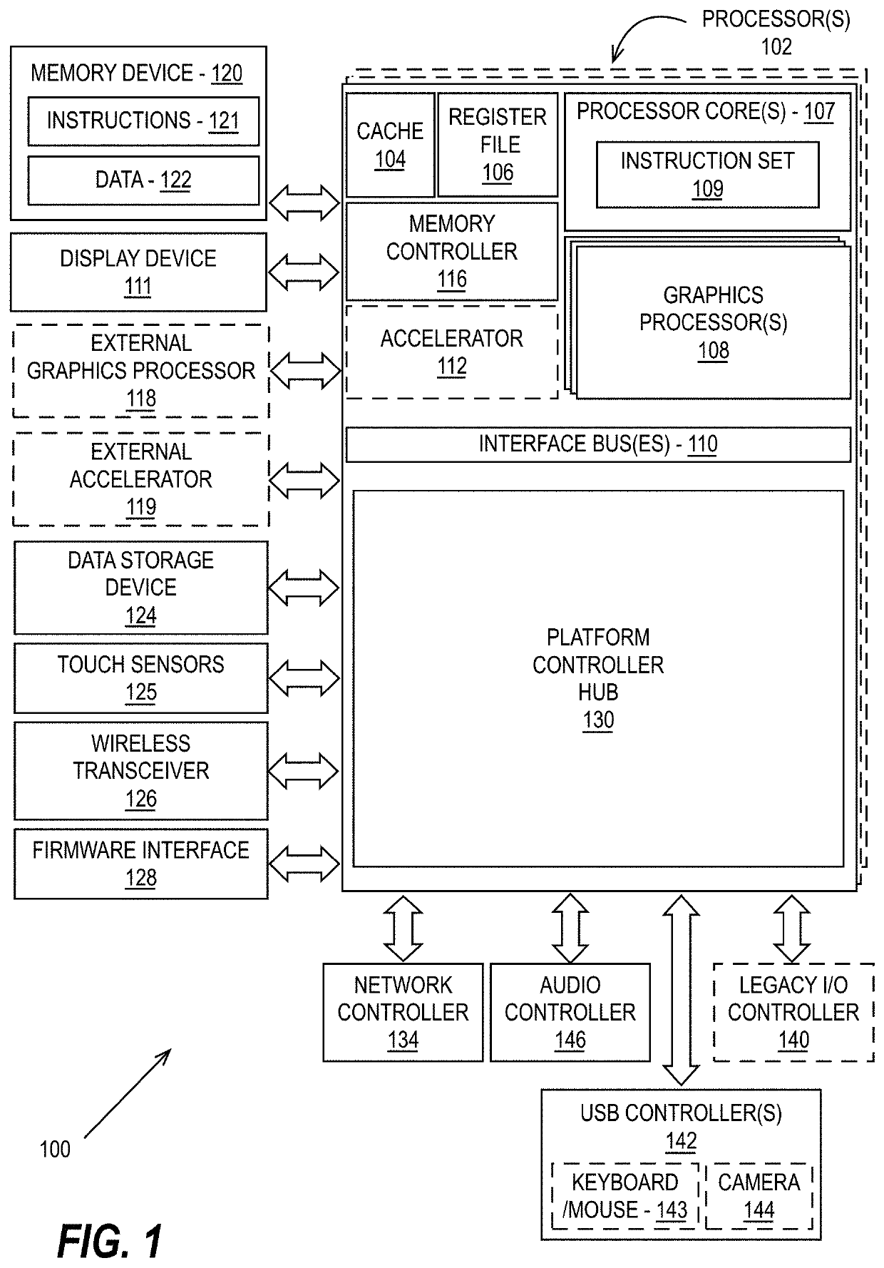
BACKGROUND OF THE DESCRIPTION[0001]Graphics processing units (GPUs) are highly threaded machines in which hundreds of threads of a program are executed in parallel to achieve high throughput. GPU thread groups are implemented in mesh shading applications to perform three-dimensional (3D) rendering. When running three-dimensional (3D) workloads on GPUs, cache settings (e.g., whether a resource can be cached, the cache policy for a resource (WC, WT etc.) and caching actions (e.g., pre-fetching, eviction, etc.) have a substantial impact on overall performance of the workload. However, choosing settings that yield a best performance for each resource is typically impossible since the best settings often cannot be determined until after the work on a resource has been completed.BRIEF DESCRIPTION OF THE DRAWINGS[0002]So that the manner in which the above recited features of the present invention can be understood in detail, a more particular description of the invention, briefly summarize...
Claims
Login to View More Application Information
Patent Timeline
 IPC IPC(8): G06F12/0893G06F12/0873G06F12/0862G06F9/30G06F9/50G06F11/30
CPCG06F12/0893G06F12/0873G06F12/0862G06F2212/1021G06F9/5016G06F11/3037G06F9/30043G06F12/0802G06F2212/601G06F2212/455G06F2212/502
Inventor SHETTY, SUDARSHANRAMCHEUNG, PING HANGANANTARAMAN, ARAVINDHSCHLUESSLER, TRAVIS
Owner INTEL CORP