Communication system and communication terminal device

Pending Publication Date: 2021-12-16
MITSUBISHI ELECTRIC CORP
View PDF0 Cites 0 Cited by
  • Summary
  • Abstract
  • Description
  • Claims
  • Application Information

AI Technical Summary

Benefits of technology

The patent invention allows for radio communication with low delay in NLOS (non-line-of-sight) networks. This means that data can be transmitted quickly and efficiently between devices without causing delays in the network.

Problems solved by technology

The RACH involves a collision risk.

Method used


Image

  • Communication system and communication terminal device
  • Communication system and communication terminal device
  • Communication system and communication terminal device

Examples


first embodiment

The First Embodiment

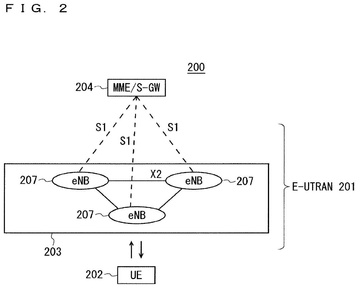
[0106]FIG. 2 is a block diagram showing an overall configuration of an LTE communication system 200 which is under discussion of 3GPP. FIG. 2 is described here. A radio access network is referred to as an evolved universal terrestrial radio access network (E-UTRAN) 201. A user equipment device (hereinafter, referred to as a “user equipment (UE)”) 202 that is a communication terminal device is capable of radio communication with a base station device (hereinafter, referred to as a “base station (E-UTRAN Node B: eNB)”) 203 and transmits and receives signals through radio communication.

[0107]Here, the “communication terminal device” covers not only a user equipment device such as a mobile phone terminal device, but also an unmovable device such as a sensor. In the following description, the “communication terminal device” may be simply referred to as a “communication terminal”.

[0108]The E-UTRAN is composed of one or a plurality of base stations 203, provided that a ...

second embodiment

[0210]The second embodiment will describe another means in which the UE preferentially selects the DU under the same CU over the DU under a different CU when the UE performs cell reselection.

[0211]In the first embodiment, when the UE compares the received power from neighboring DUs, regarding all of the neighboring DUs, the UE determines which DU has maximum received power. In contrast, in the second embodiment, when the UE compares the received power of the DUs, regarding all of the DUs under the same CU, the UE compares the received power of the DU with a predetermined threshold B so as to narrow down cell reselection target candidates.

[0212]When there are DUs having received power of the threshold B or greater, the UE regards only such DUs, specifically the DUs having received power of the threshold B or greater, as the cell reselection target candidates, and then determines which DU has maximum received power.

[0213]When there are no DUs having received power of the threshold B o...

third embodiment

[0230]The first and second embodiments describe a means of preferentially selecting the DU under the same CU over the DU under a different CU when cell reselection is performed in the system of the CU-DU split configuration. The third embodiment will describe a means of preferentially selecting a cell in the same RAN-based notification area (RNA (see Non-Patent Document 16)) over a cell in a different RNA, not only in the system of the CU-DU split configuration.

[0231]FIG. 19 is a diagram illustrating an example of operation in which the UE performs cell reselection between the base stations in the RNAs.

[0232]According to the example of FIG. 19, base station #1-1, base station #1-2, and base station #1-3 belong to RNA #1. Base station #2-1 and base station #2-2 belong to RNA #2. The UE is in the state of RRC_INACTIVE after being connected to base station #1-1, and subsequently intends to be restored to the state of RRC_CONNECTED by performing cell reselection. The position of the UE ...


PUM


Abstract

A communication system includes a plurality of base stations, and a communication terminal device configured to perform radio communication with the plurality of base stations. Each of the plurality of base stations includes a plurality of distributed units (DUs) configured to perform radio communication with the communication terminal device, and a central unit (CU) configured to control the plurality of DUs. When the communication terminal device selects a connection target DU, the communication terminal device preferentially selects the DU belonging to an immediately preceding CU being the CU to which the DU having been connected in an immediately preceding case belongs over the DU belonging to another CU.

Description

TECHNICAL FIELD[0001]The present invention relates to a radio communication technology.BACKGROUND ART[0002]The 3rd generation partnership project (3GPP), the standard organization regarding the mobile communication system, is studying communication systems referred to as long term evolution (LTE) regarding radio sections and system architecture evolution (SAE) regarding the overall system configuration including a core network and a radio access network which is hereinafter collectively referred to as a network as well (for example, see Non-Patent Documents 1 to 5). This communication system is also referred to as 3.9 generation (3.9 G) system.[0003]As the access scheme of the LTE, orthogonal frequency division multiplexing (OFDM) is used in a downlink direction and single carrier frequency division multiple access (SC-FDMA) is used in an uplink direction. Further, differently from the wideband code division multiple access (W-CDMA), circuit switching is not provided but a packet co...

Claims


Application Information

Patent Timeline
IPC IPC(8): H04W36/08H04W36/10
CPCH04W36/08H04W36/10H04W48/16H04W88/085H04W48/20H04W36/30
Inventor HIRAMATSU, DAISUKESHIMODA, TADAHIRO
Owner MITSUBISHI ELECTRIC CORP
Why Eureka
Try Eureka