Method and device used in wireless communication node

Pending Publication Date: 2021-02-18
SHANGHAI LANGBO COMM TECH CO LTD
View PDF0 Cites 2 Cited by
  • Summary
  • Abstract
  • Description
  • Claims
  • Application Information

AI Technical Summary

Benefits of technology

The new NR (Open RAT) V2X system is designed to meet growing traffic demands with faster data speeds, increased reliability, and better positioning. It also has the ability to work with different technologies. The switch from LTE to NR will focus on supporting various working modes, such as unicast, groupcast, and broadcast.

Problems solved by technology

At present, the working mode of LTE V2X system is limited to broadcast transmission.
However, when two terminals in D2D or V2X communications are not far from each other, the above-mentioned transmitting power determined based on the pathloss between Uu interfaces will result in power wastes of the terminals.

Method used


Image

  • Method and device used in wireless communication node
  • Method and device used in wireless communication node
  • Method and device used in wireless communication node

Examples


embodiment 1

[0104]Embodiment 1 illustrates a flowchart of a first signaling, as shown in FIG. 1. In step 100 illustrated by FIG. 1, each box represents a step.

[0105]In Embodiment 1, the first node in the present disclosure receives K1 first-type radio signals in step 101, K1 being a positive integer greater than 1; transmits a first signaling in step 102; receives a second signaling in step 103; and transmits a first radio signal in step 104; the first signaling is used to indicate K2 first-type radio signal(s) out of the K1 first-type radio signals, K2 being a positive integer no greater than the K1; the second signaling is used to indicate K3 first-type radio signal(s) out of the K1 first-type radio signals, K3 being a positive integer no greater than the K1; the first signaling is used by a transmitter of the second signaling for determining the K3 first-type radio signal(s); the K3 first-type radio signal(s) is(are) respectively used to determine K3 pathloss(es), and the K3 pathloss(es) is(...

embodiment 2

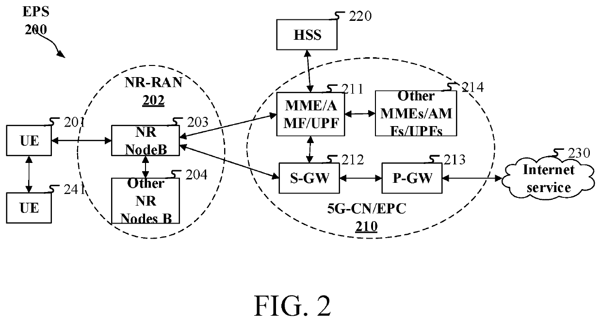
[0196]Embodiment 2 illustrates a schematic diagram of a network architecture, as shown in FIG. 2.

[0197]FIG. 2 is a diagram illustrating a network architecture 200 of 5G NR, Long-Term Evolution (LTE), and Long-Term Evolution Advanced (LTE-A) systems. The 5G NR or LTE network architecture 200 may be called an Evolved Packet System (EPS) 200, which may comprise one or more UEs 201, a UE 241 in sidelink communication with the UE 201, an NG-RAN 202, an Evolved Packet Core / 5G-Core Network (EPC / 5G-CN) 210, a Home Subscriber Server (HSS) 220 and an Internet Service 230. The EPS 200 may be interconnected with other access networks. For simple description, the entities / interfaces are not shown. As shown in FIG. 2, the EPS 200 provides packet switching services. Those skilled in the art will readily understand that various concepts presented throughout the present disclosure can be extended to networks providing circuit switching services. The NG-RAN 202 comprises an NR node B (gNB) 203 and ot...

embodiment 3

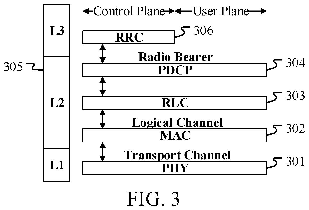
[0214]Embodiment 3 illustrates a schematic diagram of a radio protocol architecture of a user plane and a control plane, as shown in FIG. 3.

[0215]FIG. 3 is a schematic diagram illustrating a radio protocol architecture of a user plane and a control plane. In FIG. 3, the radio protocol architecture for a UE and a base station (gNB or eNB) is represented by three layers, which are a layer 1, a layer 2 and a layer 3, respectively. The layer 1 (L1) is the lowest layer and performs signal processing functions of various PHY layers. The L1 is called PHY 301 in the present disclosure. The layer 2 (L2) 305 is above the PHY 301, and is in charge of the link between the UE and the gNB via the PHY 301. In the user plane, L2 305 comprises a Medium Access Control (MAC) sublayer 302, a Radio Link Control (RLC) sublayer 303 and a Packet Data Convergence Protocol (PDCP) sublayer 304. All the three sublayers terminate at the gNBs of the network side. Although not described in FIG. 3, the UE may comp...


PUM


Abstract

The present disclosure discloses a method and device used in wireless communication node. A first node first receives K1 first-type radio signals, and then transmits a first signaling, receives a second signaling and transmits a first radio signal in sequence; the first signaling is used to indicate K2 first-type radio signal(s) of the K1 first-type radio signals, while the second signaling is used to indicate K3 first-type radio signal(s) of the K1 first-type radio signals; the K3 first-type radio signal(s) is(are) respectively used to determine K3 pathloss(es). By designing a mechanism of interaction between a terminal and a base station, and the channel quality of sidelink detected by the terminal to determine a transmitting power of sidelink, the present disclosure manages to reduce interference to a cellular network while ensuring sidelink performance, thus improving the system's overall performance.

Description

CROSS REFERENCE TO RELATED APPLICATIONS[0001]This application is a continuation of International Application No. PCT / CN2019 / 104047, filed Sep. 2, 2019, claims the priority benefit of Chinese Patent Application No. 201811092849.0, filed on Sep. 18, 2018, the full disclosure of which is incorporated herein by reference.BACKGROUNDTechnical Field[0002]The present disclosure relates to transmission methods and devices in wireless communication systems, and in particular to a communication method and device for sidelink in wireless communications.Related Art[0003]Application scenarios of future wireless communication systems are becoming increasingly diversified, and different application scenarios have different performance demands on systems. In order to meet different performance requirements of various application scenarios, the 3rd Generation Partner Project (3GPP) Radio Access Network (RAN) #72 plenary decided to conduct the study of New Radio (NR), or what is called fifth Generatio...

Claims


Application Information

Patent Timeline
IPC IPC(8): H04W72/04H04W72/08H04B7/0426H04L5/00H04B17/309
CPCH04W72/046H04W72/085H04B17/309H04L5/0053H04B7/0426H04W4/40H04W4/70H04B7/0617H04B7/026H04W52/242H04W52/383H04W52/243H04B17/318H04L5/0048H04W72/542
Inventor JIANG, QIZHANG, XIAOBOYANG, LIN
Owner SHANGHAI LANGBO COMM TECH CO LTD
Why Eureka
Try Eureka