Method and device used in wireless communication node

a wireless communication and node technology, applied in the direction of machine-to-machine/machine-type communication services, signalling characterisation, transportation and packaging, etc., can solve the problems of sidelink transmission resource restrictions, achieve precise positioning, improve throughput and reliability, and reduce latency

Active Publication Date: 2021-01-07
HONOR DEVICE CO LTD
View PDF0 Cites 0 Cited by
  • Summary
  • Abstract
  • Description
  • Claims
  • Application Information

AI Technical Summary

Benefits of technology

The patent text describes a method to improve sidelink communication in a 5G NR system by addressing the issue of fragmentary resource configurations. The method allows for sidelink transmissions in a specific beam direction of downlink symbols through spatially orthogonal beams, thereby expanding resources for sidelink transmissions without influencing the existing system. Additionally, the method allows for sidelink communication in an idle beam direction of a first symbol set, thus acquiring more opportunities of sidelink communication. These technical features enable more efficient and reliable sidelink communication in the 5G NR system.

Problems solved by technology

In one embodiment, a problem to be solved in the present disclosure is that fragmentary uplink and downlink resource configurations in 5G NR system will lead to restrictions over sidelink transmission resources.

Method used


Image

  • Method and device used in wireless communication node
  • Method and device used in wireless communication node
  • Method and device used in wireless communication node

Examples


embodiment 1

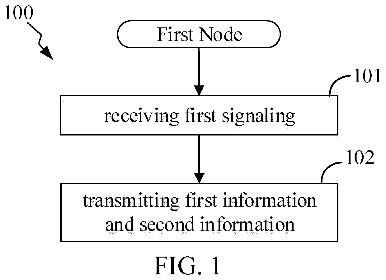
[0163]Embodiment 1 illustrates a flowchart of transmission of a first signaling, first information and second information, as shown in FIG. 1.

[0164]In Embodiment 1, when a first node in the present disclosure is in coverage, the first node receives a first signaling, the first signaling being used for indicating a first time unit format in the present disclosure; and transmits first information and second information; the first information is used for indicating a first symbol set and a second symbol set in the present disclosure; the first symbol set and the second symbol set respectively comprise a positive integer number of multicarrier symbol(s); each multicarrier symbol in the first symbol set corresponds to first-type symbols in the first time unit format, while each multicarrier symbol in the second symbol set corresponds to second-type symbols in the first time unit format; the second information is used for indicating a first spatial Rx parameter group associated with the f...

embodiment 2

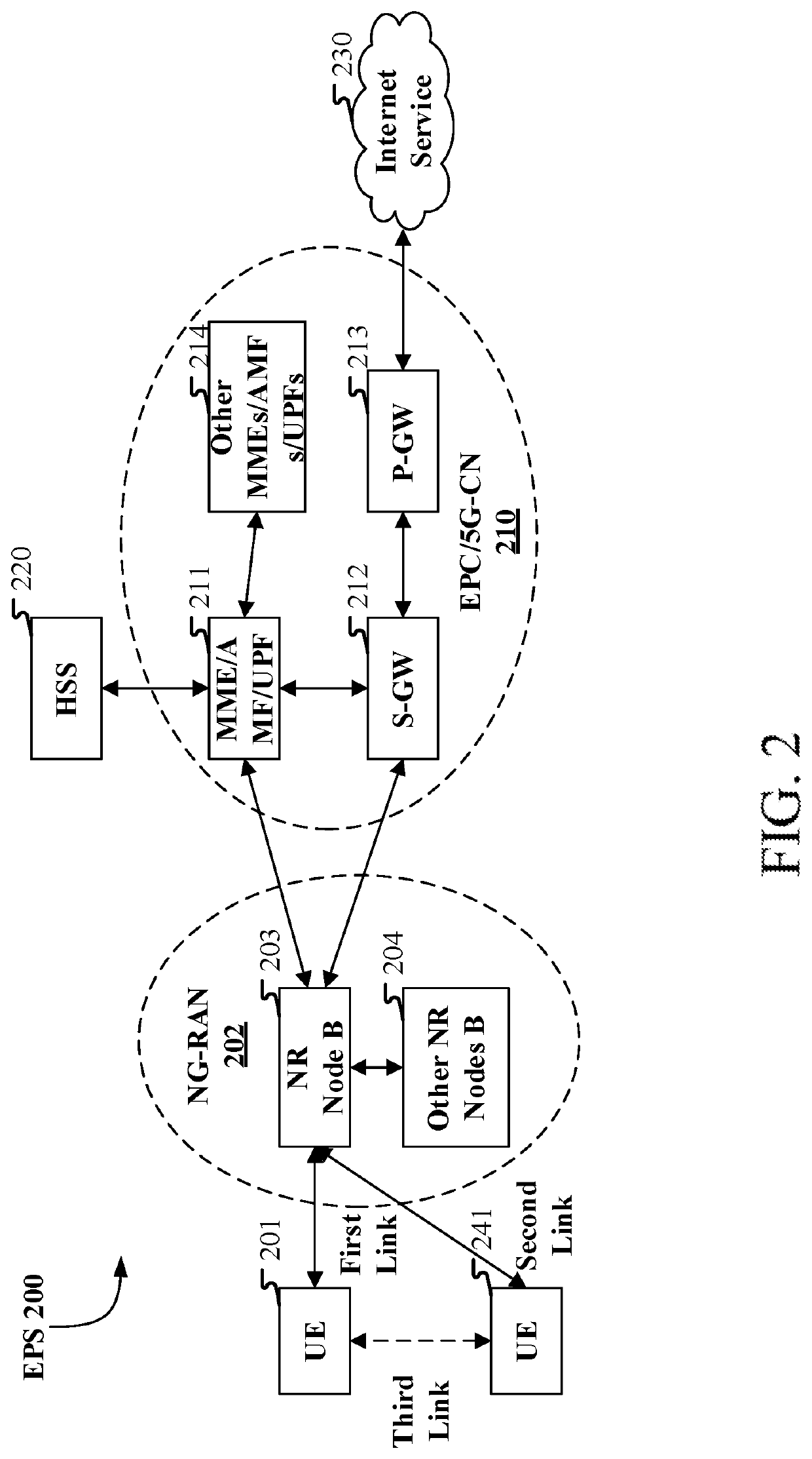
[0232]Embodiment 2 illustrates a schematic diagram of a network architecture, as shown in FIG. 2.

[0233]FIG. 2 is a diagram illustrating a network architecture 200 of 5G NR, Long-Term Evolution (LTE) and Long-Term Evolution Advanced (LTE-A) systems. The NR 5G or LTE network architecture 200 may be called an Evolved Packet System (EPS) 200 or other appropriate terms. The EPS 200 may comprise one or more UEs 201 / 241, an NG-RAN 202, an Evolved Packet Core / 5G-Core Network (EPC / 5G-CN) 210, a Home Subscriber Server (HSS) 220 and an Internet Service 230. The EPS 200 may be interconnected with other access networks. For simple description, the entities / interfaces are not shown. As shown in FIG. 2, the EPS 200 provides packet switching services. Those skilled in the art will readily understand that various concepts presented throughout the present disclosure can be extended to networks providing circuit switching services or other cellular networks. The NG-RAN 202 comprises an NR node B (gNB)...

embodiment 3

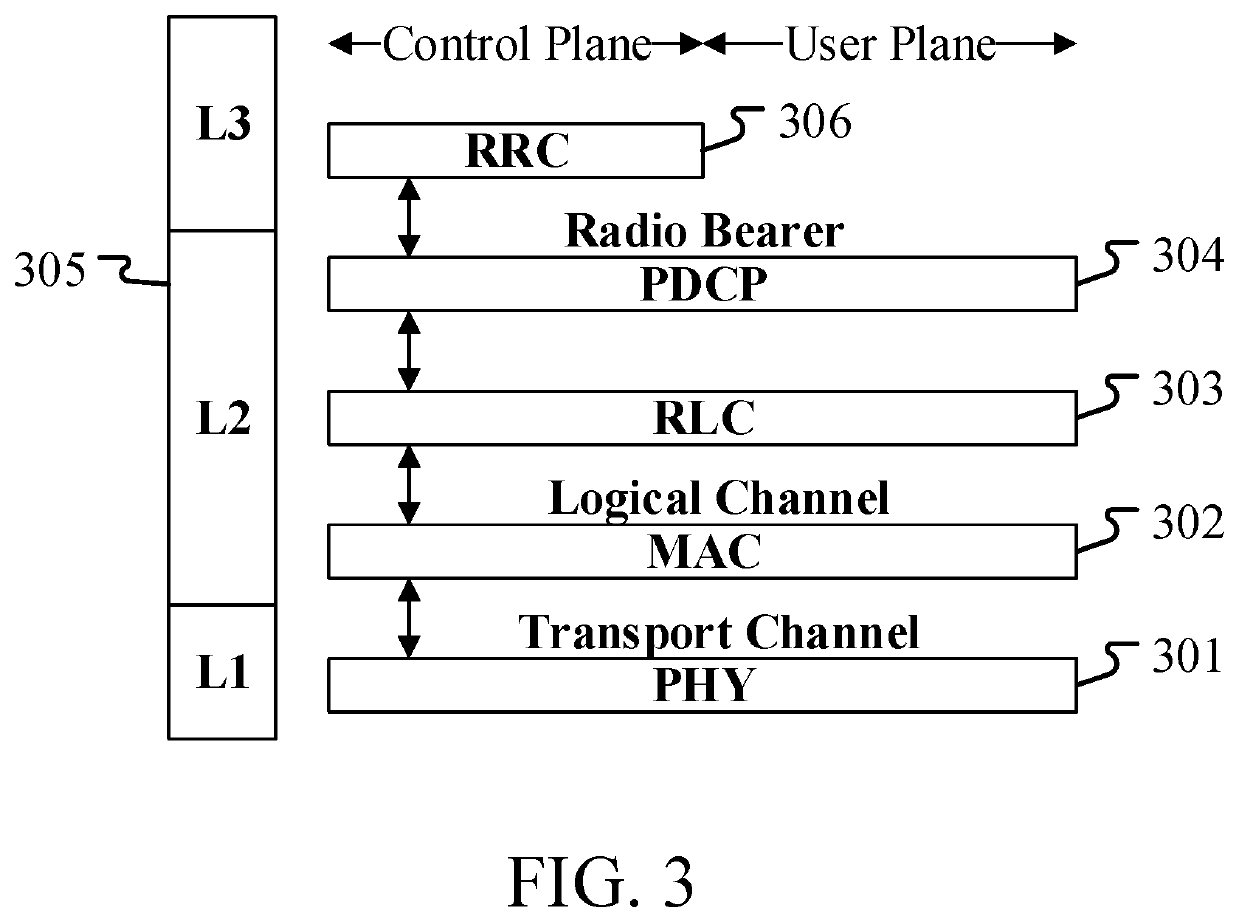
[0254]Embodiment 3 illustrates a schematic diagram of a radio protocol architecture of a user plane and a control plane, as shown in FIG. 3.

[0255]FIG. 3 is a schematic diagram illustrating a radio protocol architecture of a user plane and a control plane. In FIG. 3, the radio protocol architecture for a UE and a base station (gNB, eNB) is represented by three layers, which are a layer 1, a layer 2 and a layer 3, respectively. The layer 1 (L1) is the lowest layer and performs signal processing functions of various PHY layers. The L1 is called PHY 301 in the present disclosure. The layer 2 (L2) 305 is above the PHY 301, and is in charge of the link between the UE and the base station via the PHY 301. In the user plane, L2 305 comprises a Medium Access Control (MAC) sublayer 302, a Radio Link Control (RLC) sublayer 303 and a Packet Data Convergence Protocol (PDCP) sublayer 304. All the three sublayers terminate at the base stations of the network side. Although not described in FIG. 3,...


PUM


Abstract

The present disclosure discloses a method and a device in a node for wireless communications. A first node receives a first signaling, the first signaling being used for indicating a first time unit format; and transmits first information and second information; herein, the first information is used for indicating a first symbol set and a second symbol set; the first symbol set and the second symbol set respectively comprise a positive integer number of multicarrier symbol(s); each multicarrier symbol in the first symbol set corresponds to first-type symbols in the first time unit format, while each multicarrier symbol in the second symbol set corresponds to second-type symbols in the first time unit format; each of the first-type symbols comprises (a) downlink symbol(s), while each of the second-type symbols comprises (an) uplink symbol(s). The present disclosure expands access to transmission resources for sidelink.

Description

CROSS REFERENCE TO RELATED APPLICATIONS[0001]This application is a continuation of International Application No. PCT / CN2019 / 085631, filed May 6, 2019, claims the priority benefit of Chinese Patent Application No. 201810528415.4, filed on May 29, 2018, the full disclosure of which is incorporated herein by reference.BACKGROUNDTechnical Field[0002]The present disclosure relates to transmission methods and devices in wireless communication systems, and in particular to a multi-antenna related transmission scheme and device in wireless communications.Related Art[0003]Application scenarios of future wireless communication systems are becoming increasingly diversified, and different application scenarios have different performance demands on systems. In order to meet different performance requirements of various application scenarios, the 3rd Generation Partner Project (3GPP) Radio Access Network (RAN) #72 plenary decided to conduct the study of New Radio (NR), or what is called fifth Gen...

Claims


Application Information

Patent Timeline
IPC IPC(8): H04L1/00H04W4/40H04W72/04H04B1/06H04B1/02
CPCH04L1/0028H04W4/40H04B1/02H04B1/06H04W72/04H04L5/0053H04W72/23H04L5/00H04W4/70H04W4/44H04W4/46H04L1/004H04L2001/0097H04W88/04H04W84/047
Inventor ZHANG, XIAOBOYANG, LIN
Owner HONOR DEVICE CO LTD
Why Eureka
Try Eureka