

Seat apparatus and seat system
- Summary
- Abstract
- Description
- Claims
- Application Information
AI Technical Summary
Benefits of technology
Problems solved by technology
Method used
Image

Examples
configuration example 1
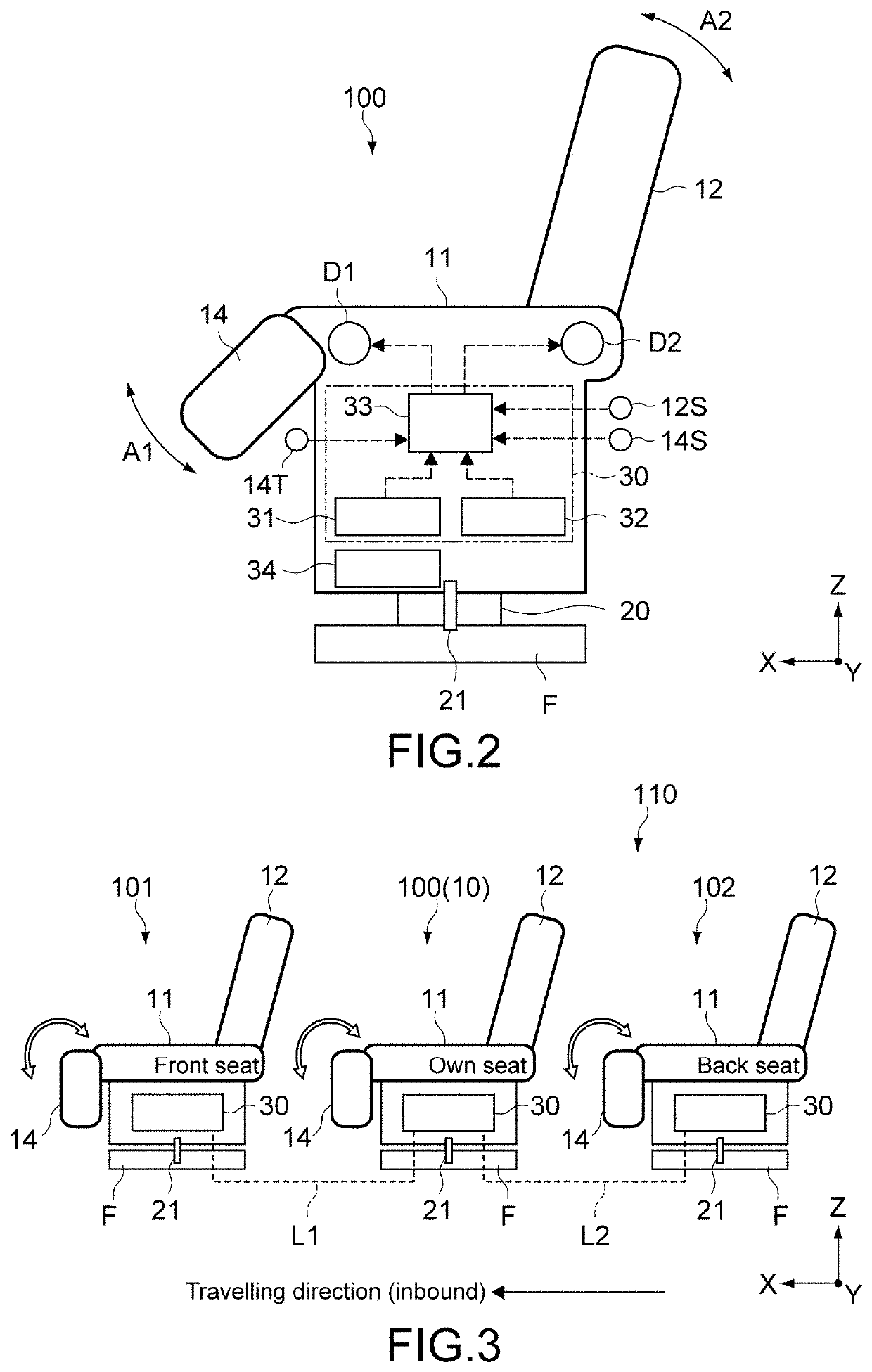
[0121]In this configuration example, the setting means includes an operation-regulation releasing unit 14T (see FIG. 2) provided in the seat body 10. The control part 33 fixes the determination result of the posture relationship with respect to the front seat 101 acquired in the first detection part 31 to the first state by operating the operation-regulation releasing unit 14T. More specifically, the operation-regulation releasing unit 14T fixes the output of the second detection circuit 6B in the own seat 100 to “1”. This allows the leg rest 14 of the own seat 100 to operate without limitation, regardless of the posture relationship between the own seat 100 and the front seat 101.
[0122]Further, when the operation-regulation releasing unit 14T is operated, the control part 33 fixes the determination result of the posture relationship with respect to the back seat 102 acquired in the second detection part 32 to the first state. More specifically, the operation-regulation releasing un...
configuration example 2
[0126]FIG. 8 is a block diagram showing the configuration of a seat system 120 according to this configuration example. In the figure, portions corresponding to those in FIG. 4 are denoted by the same reference symbols, and description thereof is omitted or simplified.
[0127]The seat system 120 according to this configuration example includes a first monitoring circuit 7A and a second monitoring circuit 7B as a setting means of releasing the operation regulation of the leg rest 14.
[0128]The first monitoring circuit 7A includes an ammeter or a voltmeter capable of detecting the energization of the second detection circuit 6B, and monitors the presence or absence of an abnormality of the power source circuit 34 in the front seat 101 via the second detection circuit 6B. The first monitoring circuit 7A is configured as a part of the control unit 30, and outputs, in the case where an abnormality is detected in the power source circuit 34 of the front seat 101, an abnormality detection sig...
configuration example 3
[0132]FIG. 9 is a block diagram showing the configuration of a seat system 130 according to this configuration example. In the figure, portions corresponding to those in FIG. 4 are denoted by the same reference symbols, and description thereof is omitted or simplified.
[0133]The seat system 130 according to this configuration example includes a power supply line 8A as a setting means for releasing the operation regulation of the leg rest 14.
[0134]The power supply line 8A includes first to third wiring members L11 to L13 connected to the first detection part 31.
[0135]The first wiring member L11 connects between the power source circuit 34 and the input terminal of the second detection circuit 6B. The second wiring member L12 connects between the output terminal of the first detection switch 5A and the input terminal of the first detection circuit 6A. The third wiring member L13 connects between the output terminal of the second detection circuit 6B and the ground terminal.
[0136]With t...
PUM
 Abstract
Description
Claims
Application Information