Information processing apparatus, control method for information processing apparatus, and storage medium
- Summary
- Abstract
- Description
- Claims
- Application Information
AI Technical Summary
Benefits of technology
Problems solved by technology
Method used
Image

Examples
Embodiment Construction
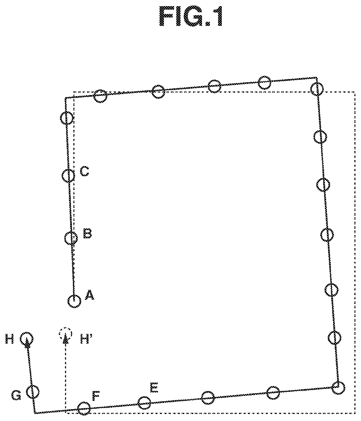
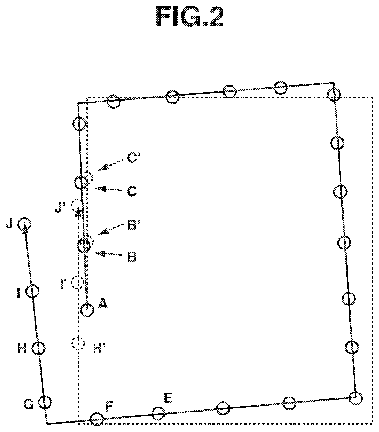
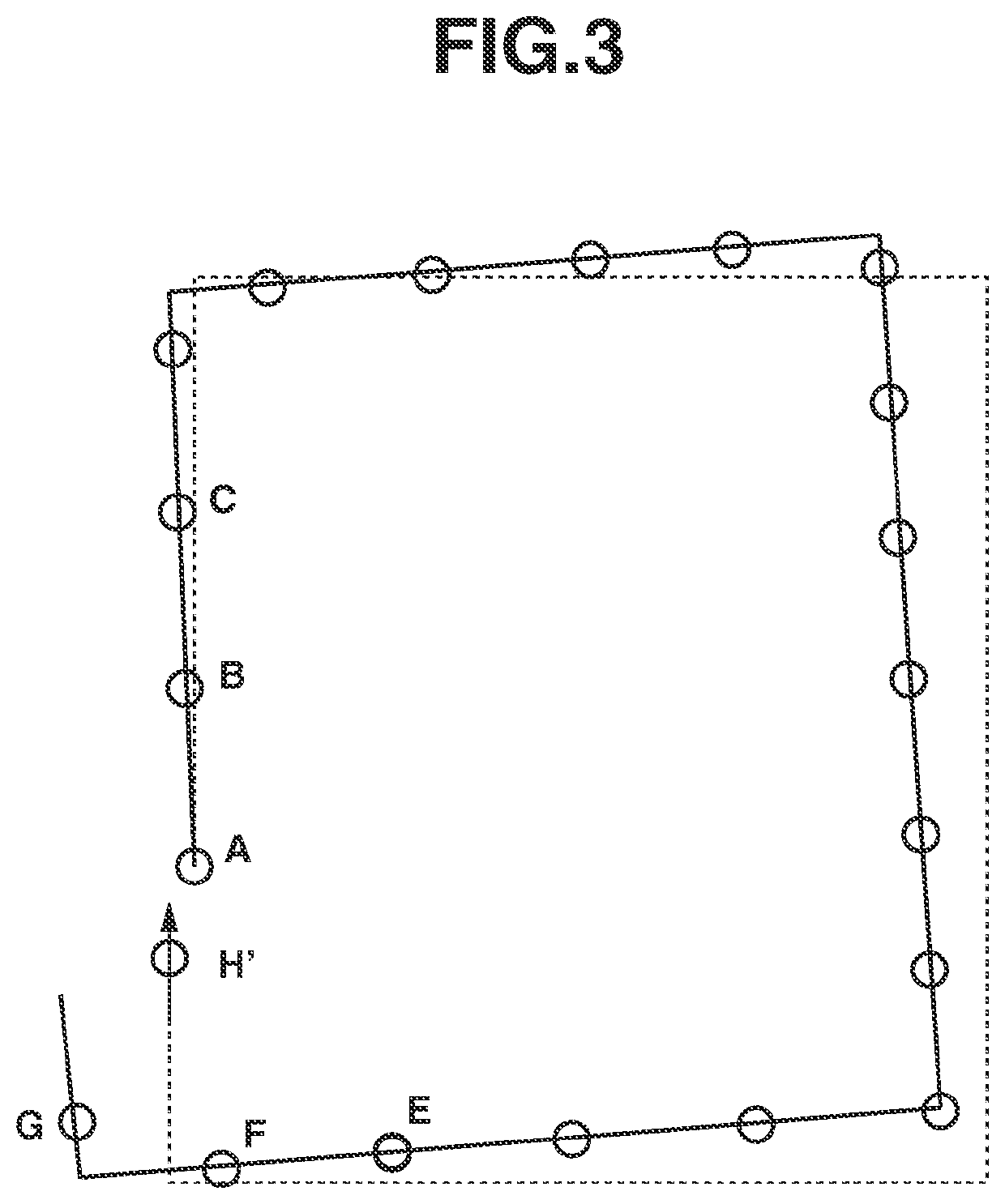
[0023]An exemplary embodiment for preventing generation of redundant measurement points that is caused by the long processing time for correcting map data when loop closing is performed will be described below.
[0024]Exemplary embodiments will be described in detail below with reference to the drawings. The following exemplary embodiments are not intended to limit the scope of the claims of the present disclosure, and not all combinations of features described in the following exemplary embodiments are essential to the present disclosure.
[0025]A moving body system, an environmental map creation system, an information processing apparatus, an information processing method, and a computer program according to a first exemplary embodiment will be described in detail below with reference to the drawings.
[0026]The first exemplary embodiment illustrates an example where a moving body on which a sensor is mounted is externally operated by a user to move in an environment and environmental m...
PUM
 Abstract
Description
Claims
Application Information
PatSnap Eureka turns technology decisions into work you can execute. Powered by our Innovation Knowledge Graph, it runs expert workflows across engineering, life sciences, materials and intellectual property. Get your review-ready output in minutes.


