
Fluid sump for accommodating a lubricating fluid

a technology of lubricating fluid and sump, which is applied in the direction of lubrication elements, machines/engines, belts/chains/gearings, etc., can solve the problems of small amount of lubricant in the sump, possible lubricant starvation, and power loss of transmission, so as to achieve low cost, high reliability, and minimal complexity

Pending Publication Date: 2022-01-06
DANA ITAL SRL
View PDF17 Cites 0 Cited by
  • Summary
  • Abstract
  • Description
  • Claims
  • Application Information

AI Technical Summary

Benefits of technology

The present disclosure is about a fluid sump for a vehicle transmission. The sump has three compartments: a first for collecting lubricating fluid, an intermediate for introducing the fluid to a rotating member, and a second for receiving the fluid from the intermediate. A floating element acts as a valve to regulate the flow of fluid between the first and intermediate compartments. This allows for a constant low fluid level in the second compartment, reducing splash fluid and energy loss. The larger amount of lubricating fluid stored in the first compartment dilutes contamination particles and replenishes the second compartment as needed to prevent rapid contamination and maintain service intervals.

Problems solved by technology

The subsequent churning and splashing are responsible for most of the transmission power losses.
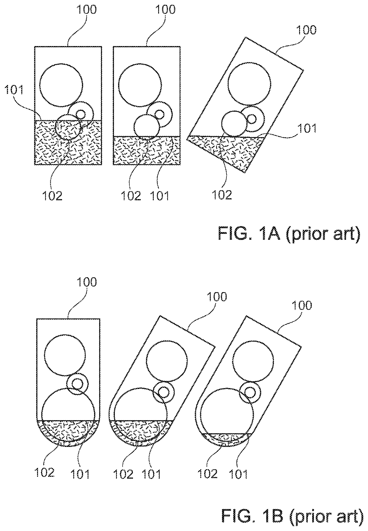
The drawback is a possible lubricant starvation when the vehicle is driven in steep slopes.
However, reducing the oil level in this way, results in a tiny amount of lubricant in the sump only as shown in FIG. 1B.
This small amount of oil is not consistent with a reasonably long service interval or with a good dilution of contaminating particles.

Method used


Image

  • Fluid sump for accommodating a lubricating fluid
  • Fluid sump for accommodating a lubricating fluid
  • Fluid sump for accommodating a lubricating fluid

Examples


first embodiment

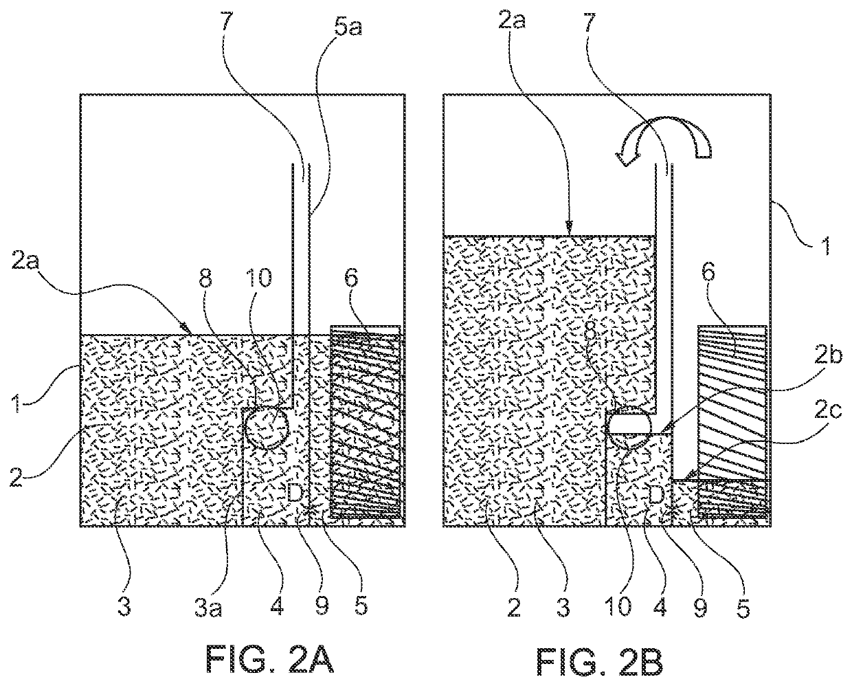
[0033]FIGS. 2A and 2B shows a fluid sump 1 according to the present disclosure. To reduce splashing, a lubricating fluid level in the fluid sump should be as low as possible. Conversely, for the sake of cleanliness and to extend service intervals, it is advisable to fill the transmission with a significant amount of lubricating fluid. The present disclosure combines these two contrasting aspects: to keep wheels draft as low as possible while ensuring maximum lubricating fluid volume in the transmission.

[0034]As shown in FIG. 2A, the fluid sump 1 accommodates a lubricating fluid 2 up to a lubricating fluid level 2a. The fluid sump 1 is divided in three leaking compartments 3, 4, 5 which are separated by a first partition wall 3a and a second partition wall 5a. The first compartment 3 and the intermediate compartment 4 are separated by the first partition wall 3a whereas the intermediate compartment 4 and the second compartment 5 are separated by the second partition wall 5a. The firs...

second embodiment

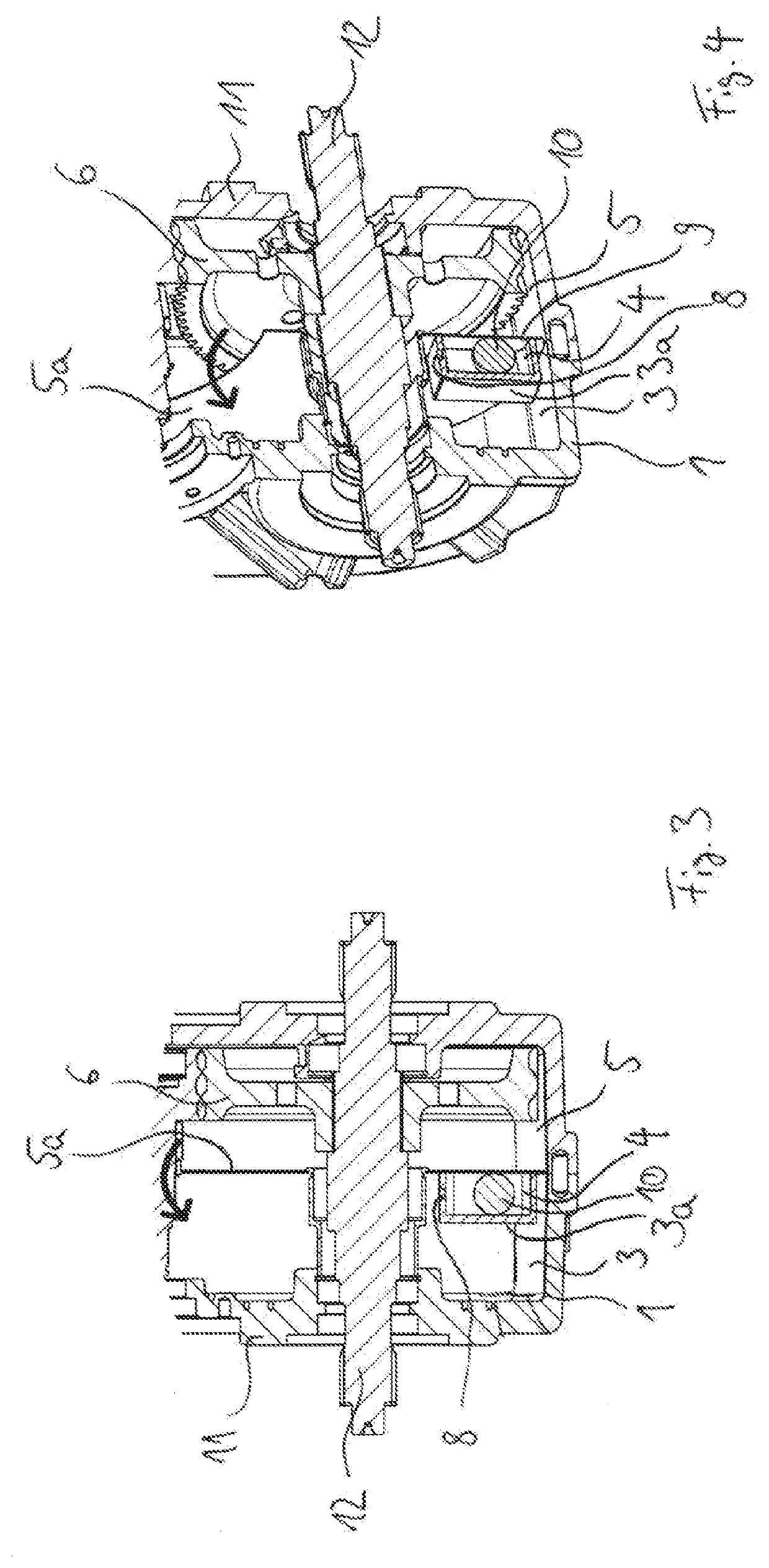
[0040]FIG. 3 shows a frontal view of a section of a gearbox comprising a fluid sump 1 according to the present disclosure. FIG. 4 shows a perspective view of the section of FIG. 3. The gearbox comprises a housing 11 with a shaft 12 extending therethrough. The lower part of the housing 11 is formed by the fluid sump 1. The fluid sump 1 of FIG. 3 is similarly constructed as the fluid sump 1 of FIGS. 2A and 2B. The fluid sump comprises a first compartment 3, an intermediate compartment 4 and a second compartment 5. The intermediate compartment 4 is separated from the first compartment 3 by a box-shaped partition wall 3a. Moreover, the intermediate compartment 4 is separated from the second compartment 5 by flat partition wall 5a which extends from the bottom of the housing 11 over the shaft 12. Since the intermediate compartment 4 has the form of a small box which is disposed at the bottom of the housing 11, in the upper part of the housing 11 the partition wall 5a directly separates t...


PUM


Abstract

A fluid sump for accommodating a lubricating fluid and transmission housing for a vehicle comprising such a fluid sump. The fluid sump may comprise a first compartment for collecting the lubricating fluid, a second compartment in which the lubricating fluid can be brought in contact with a rotating member, and an intermediate compartment having a first opening for introducing the lubricating fluid from the first compartment into the intermediate compartment, a second opening for introducing the lubricating fluid from the intermediate compartment into the second compartment, and a floating element. In one or more examples, the first opening can be opened and closed by the floating element, and the first compartment, the intermediate compartment and the second compartment are provided with ambient pressure.

Description

CROSS-REFERENCE TO RELATED APPLICATION[0001]The present application claims priority to German Utility Model Application Serial No. 20 2020 103 852.4, entitled “FLUID SUMP FOR ACCOMMODATING A LUBRICATING FLUID,” and filed on Jul. 2, 2020. The entire contents of the above-listed application are hereby incorporated by reference for all purposes.TECHNICAL FIELD[0002]The present disclosure is related to a fluid sump for accommodating a lubricating fluid, for instance for use in an area of a vehicle transmission. The present disclosure is also related to a transmission housing for a vehicle transmission comprising a fluid sump.BACKGROUND AND SUMMARY[0003]Low cost transmissions usually rely on oil splashing to guarantee gears and bearings lubrication. Splash lubrication is a consolidated technology among off-highway vehicles. Minimal complexity together with high reliability are the main advantages of this lubrication arrangement. To guarantee a minimal lubrication flow at whichever slope ...

Claims


Application Information

Patent Timeline
Patent Type & Authority Applications(United States)
IPC IPC(8): F01M11/00
CPCF01M11/0004F01M2011/0058F01M2011/0041F16H57/0457F16H57/0452F16H57/0443F16H57/0445F16H57/0424F16H57/0447F16H57/0453F16H57/0409
Inventor RINALDI, PIER PAOLOGIOIA, NICOLETTA
Owner DANA ITAL SRL
Learn More