

Cashier Station Vertical Air Curtain Attachment
- Summary
- Abstract
- Description
- Claims
- Application Information
AI Technical Summary
Benefits of technology
Problems solved by technology
Method used
Image

Examples
Embodiment Construction
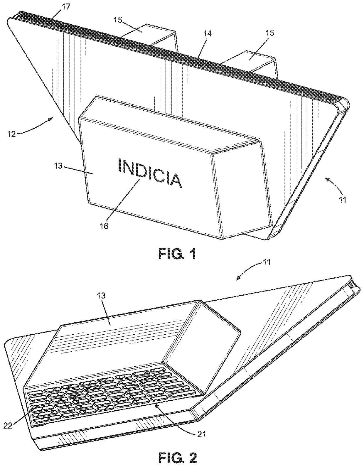
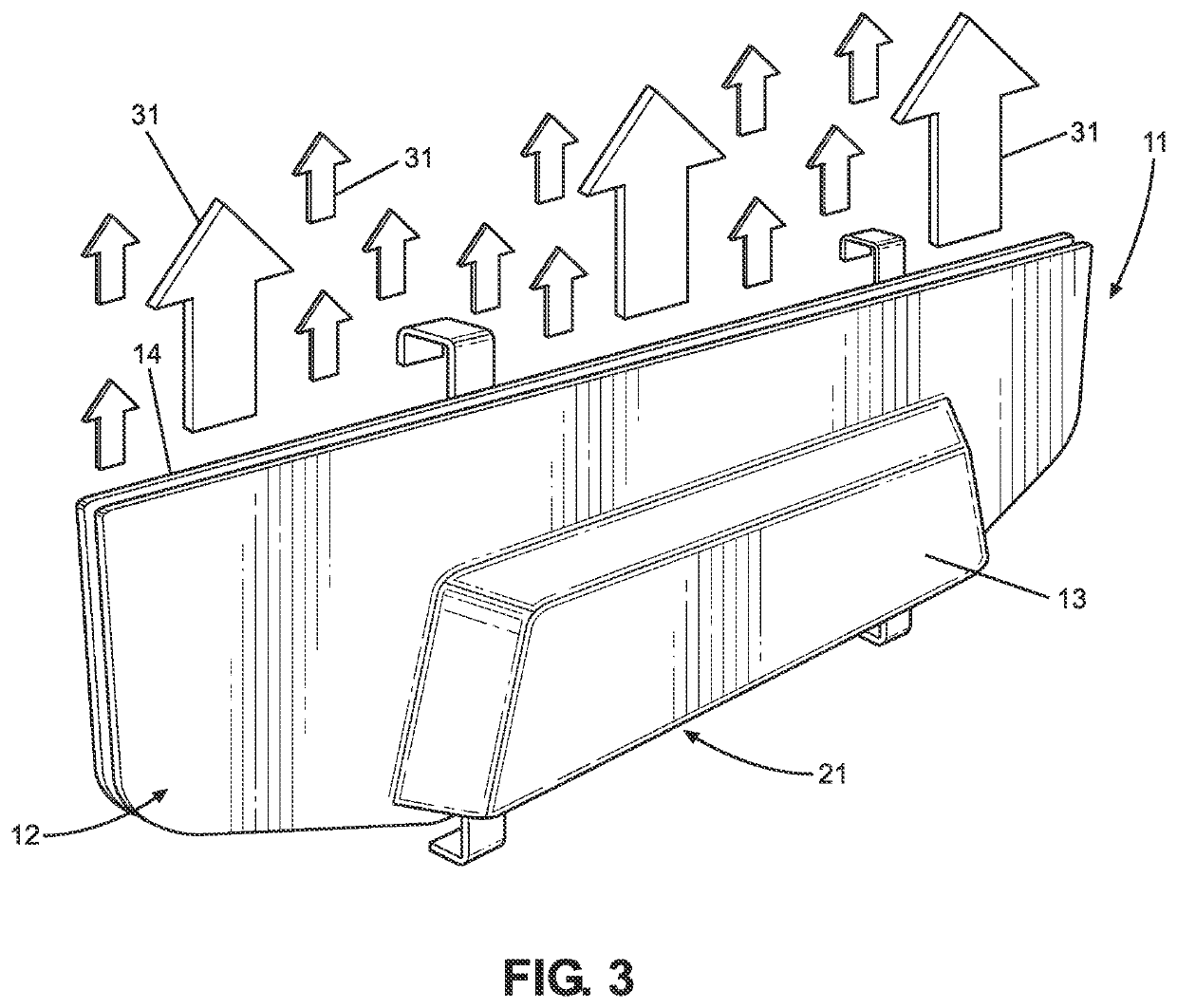
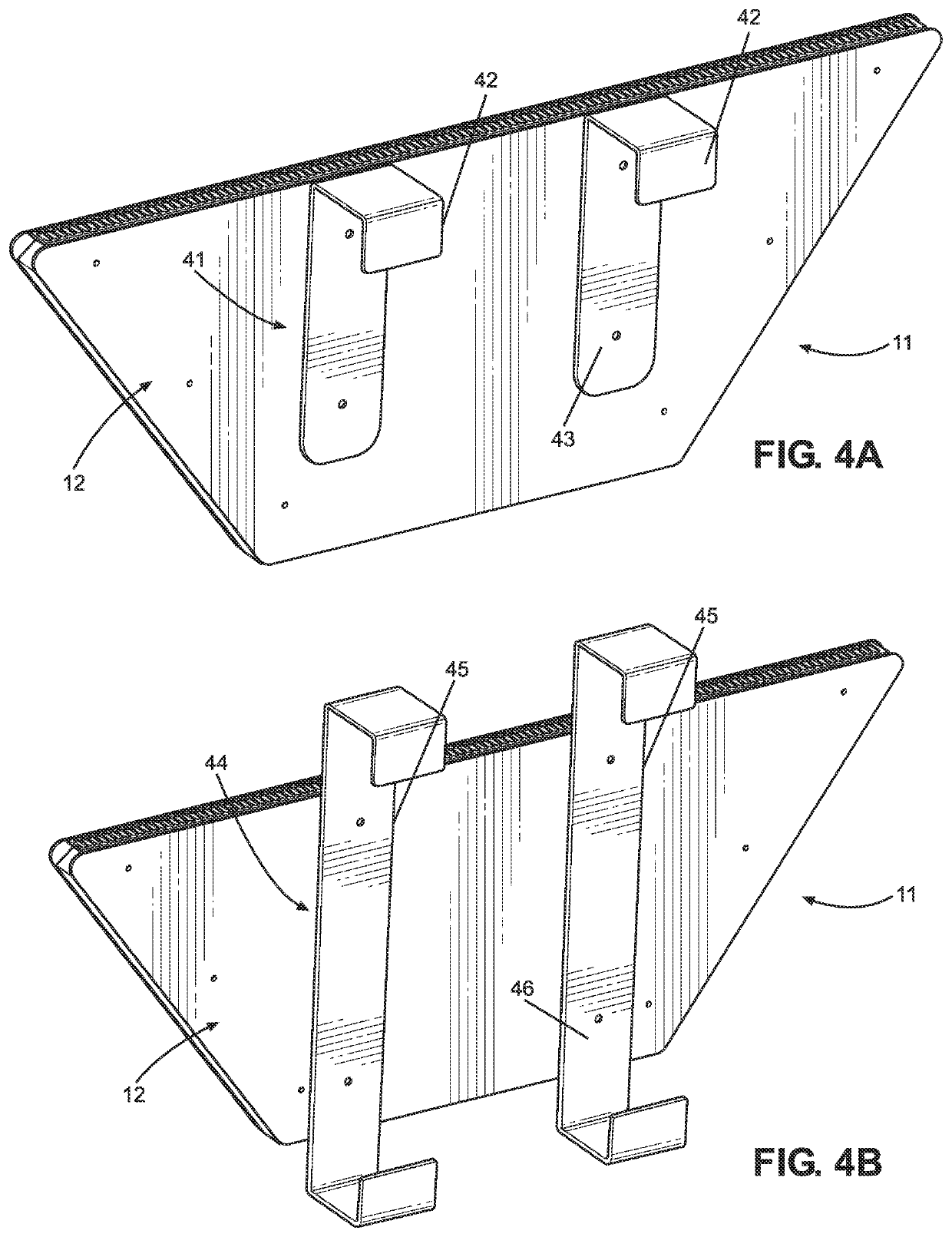
[0025]Reference is made herein to the attached drawings. Like reference numerals are used throughout the drawings to depict like or similar elements of the cashier station shield. For the purposes of presenting a brief and clear description of the present invention, the preferred embodiment will be discussed as used as a cashier station attachment for creating an air curtain between a customer and a retailer. The figures are intended for representative purposes only and should not be considered to be limiting in any respect.
Definition
[0026]An “air curtain” is an invisible and continuously blown curtain of air that creates a barrier or shield. The air curtain diverts airborne hazards, including insects, contaminants, particles, pathogens, and respiratory droplets away from a location. Air curtains are recommended by the FDA as an effective means of protection from airborne hazards, as enumerated in Food Code 6-202.15(D)(2). As described herein, air shields prevent insects, contaminan...
PUM
 Abstract
Description
Claims
Application Information