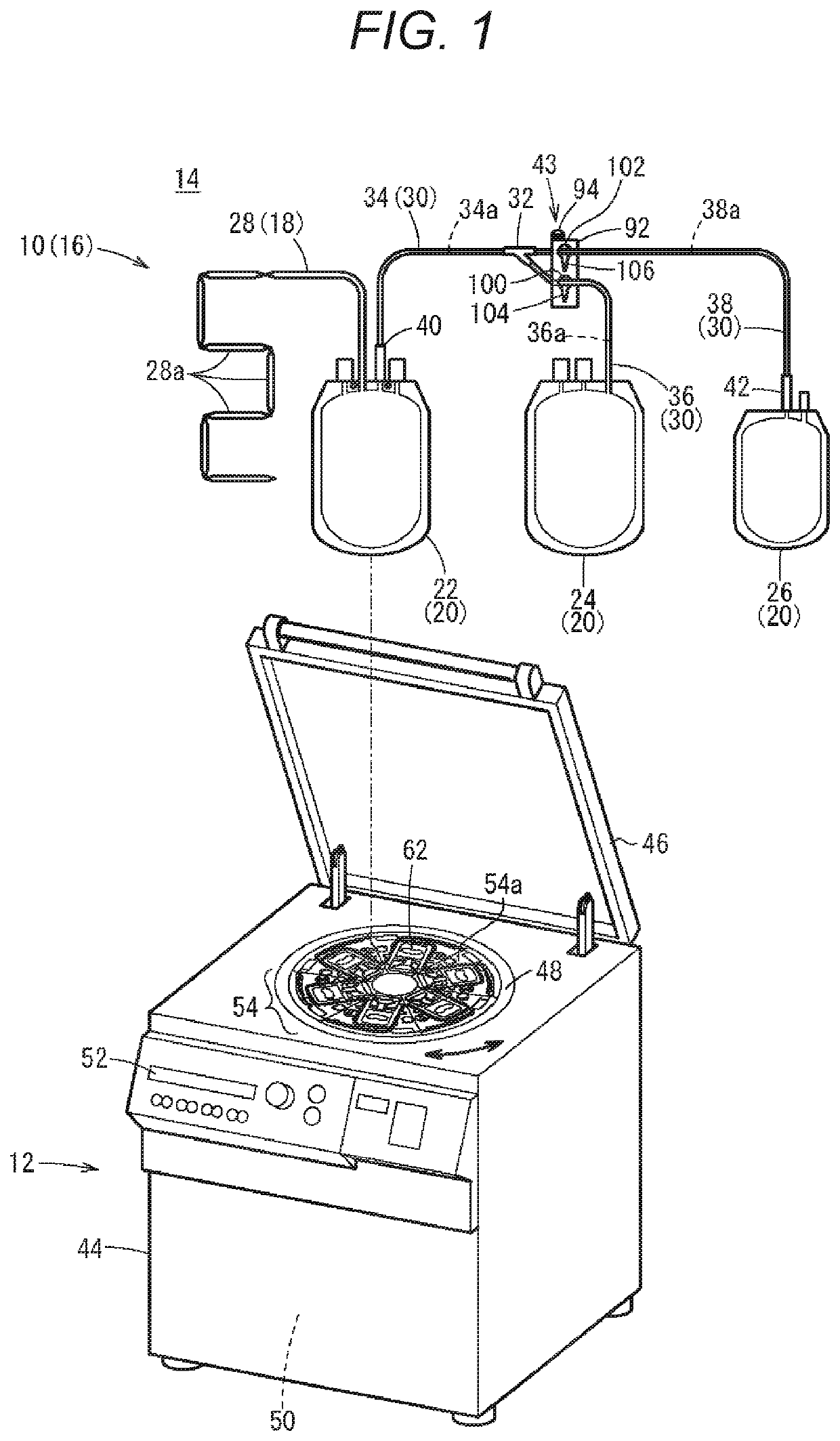
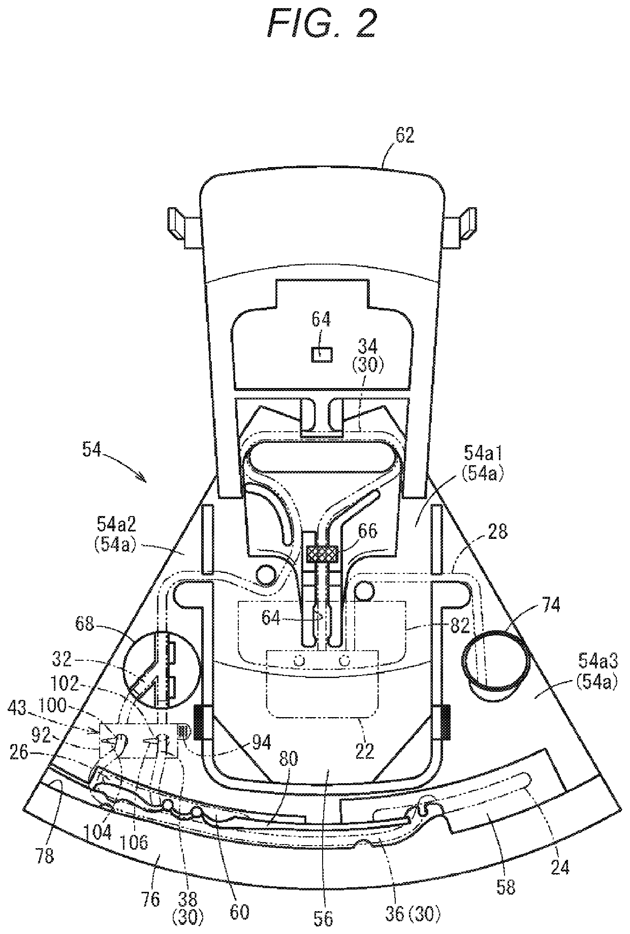
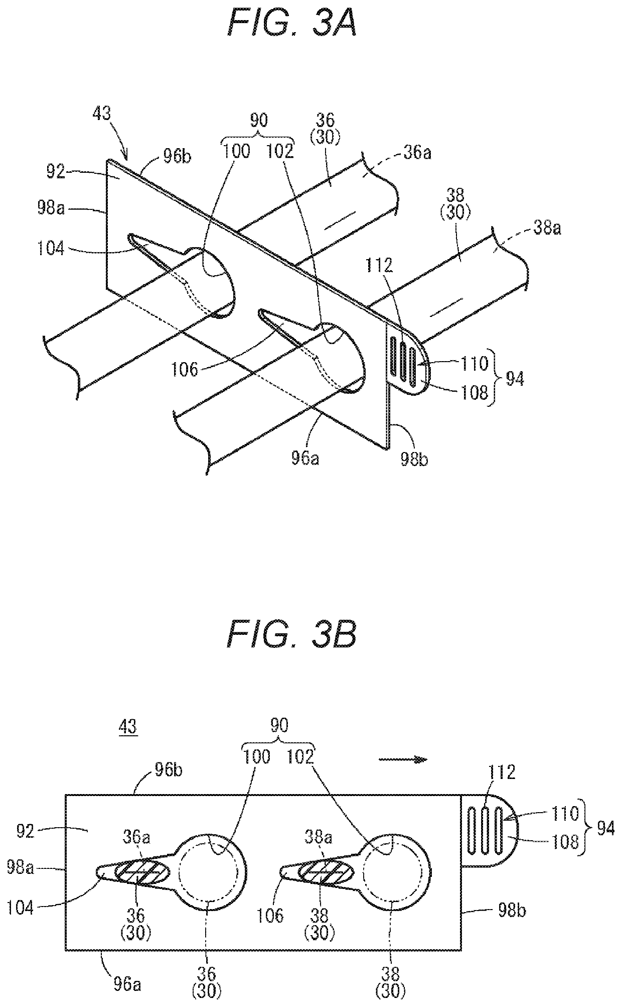
Blood bag system and clamp
- Summary
- Abstract
- Description
- Claims
- Application Information
AI Technical Summary
Benefits of technology
Problems solved by technology
Method used
Image
Examples
first modification
[0100](First Modification)
[0101]Next, a clamp 43A according to a first modification will be described. Note that the same components as those of the clamp 43 described above are denoted by the same reference signs in the clamp 43A according to the present modification, and the description thereof will be omitted. The same applies to a clamp 43B according to a second modification and a clamp 43C according to a third modification which will be described later.
[0102]As illustrated in FIG. 7, the clamp 43A according to the first modification includes a first slit 150 and a second slit 152, instead of the first slit 104 and the second slit 106 of the clamp 43 described above. The first slit 150 is different from the first slit 104 only in terms of an extending direction from the first insertion hole 100. That is, the first slit 150 extends so as to be inclined to the first long side 96a side from the first insertion hole 100 toward the first short side 98a.
[0103]The second slit 152 is d...
second modification
[0106](Second Modification)
[0107]Next, the clamp 43B according to the second modification will be described. As illustrated in FIGS. 8A and 8B, the clamp 43B has a rectangular base 154 and an operation section 156 provided on one long side of the base 154. The base 154 is formed with the insertion holes 90 (first insertion hole 100 and second insertion hole 102). A wall section forming the first insertion hole 100 is provided with a first slit 158, and a wall section forming the second insertion hole 102 is provided with a second slit 160.
[0108]Each of the first slit 158 and the second slit 160 extends along a direction (lateral direction of the base 154) orthogonal to an array direction of the first insertion hole 100 and the second insertion hole 102. Specifically, the first slit 158 extends from the first insertion hole 100 toward the other long side (side opposite to the operation section 156). A shape of the first slit 158 is similar to the shape of the first slit 104 described...
third modification
[0115](Third Modification)
[0116]Next, the clamp 43C according to the third modification will be described. As illustrated in FIG. 9, the clamp 43C includes a base 172 formed with one insertion hole 170 through which both the second tube 36 and the third tube 38 are inserted. The base 172 is formed in a rectangular plate shape using a hard resin material. That is, the base 172 includes a first long side 174a and a second long side 174b extending in parallel with each other, and a first short side 176a and a second short side 176b extending in parallel with each other.
[0117]The insertion hole 170 is located at the center of the base 172 and extends in the longitudinal direction of the base 172. A first slit 180 for pressing the outer circumferential surface of the second tube 36 inward so as to close the second flow channel 36a of the second tube 36 is provided at one end (end on the first short side 176a side) of the base 172.
[0118]The first slit 180 linearly extends from the inserti...
PUM
 Abstract
Description
Claims
Application Information
 - R&D
- Intellectual Property
- Life Sciences
- Materials
- Tech Scout
- Unparalleled Data Quality
- Higher Quality Content
- 60% Fewer Hallucinations
Browse by: Latest US Patents, China's latest patents, Technical Efficacy Thesaurus, Application Domain, Technology Topic, Popular Technical Reports.
© 2025 PatSnap. All rights reserved.Legal|Privacy policy|Modern Slavery Act Transparency Statement|Sitemap|About US| Contact US: help@patsnap.com


