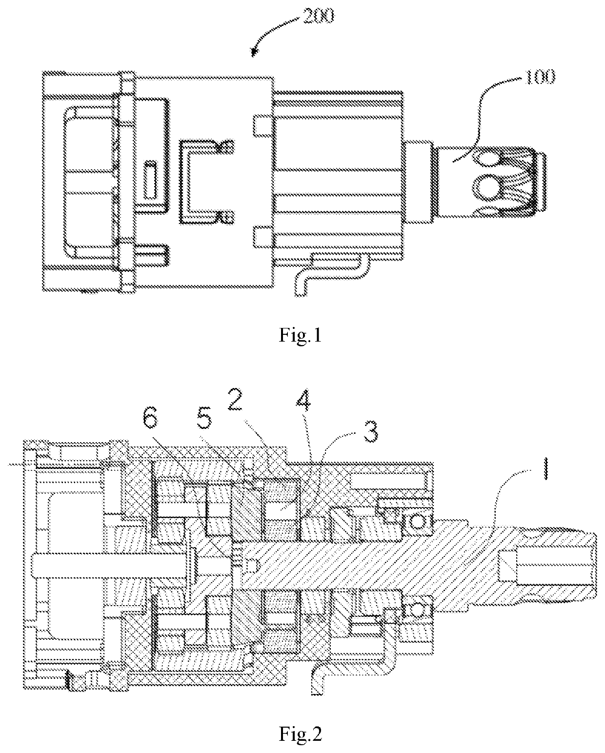
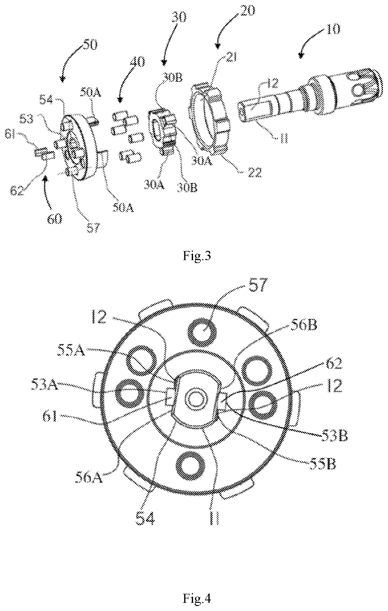
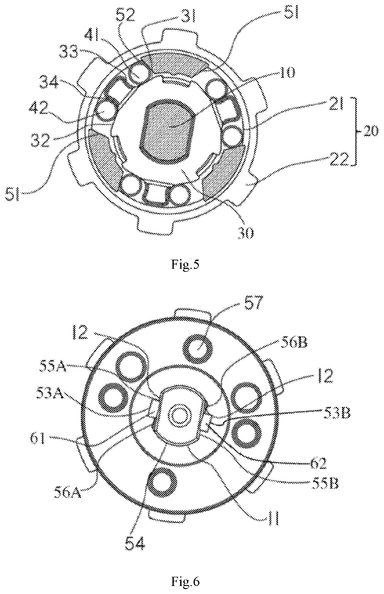
Power tool

a power tool and power technology, applied in the direction of belt/chain/gearing, yielding coupling, belt/chain/gearing, etc., can solve the problems of strong impact, hidden safety hazards, and detrimental to the life of power tools, and achieve good shock absorption and noise reduction, prolong the life of the power tool, and avoid damage to the planet carrier and the output shaft

Inactive Publication Date: 2022-01-20
TECHTRONIC CORDLESS GP
View PDF0 Cites 0 Cited by
  • Summary
  • Abstract
  • Description
  • Claims
  • Application Information

AI Technical Summary

Benefits of technology

[0003]In view of the above-mentioned shortcomings of the art, the disclosure provides a power tool with a novel design and technical effects.
[0007]Comparing with prior art, the power tool according to the disclosure has many advantages. For example, by using the provided buffer mechanism as the impact surface, the effect of shock absorption and noise reduction is good, and it may even achieve no impact sound. Due to existence of the buffer mechanism, undesired force between the planet carrier and the output shaft is greatly reduced, damage to the planet carrier and the output shaft is avoided, and the life of the power tool is prolonged. At the same time, it also reduces or eliminates noise generated by the impact, and increases comfort of the personnel in the working environment of the power tool. The buffer mechanism structure can be a single member, rather than an assembly of two or more components, so its structure is very simple, the cost is low, and it is easy to install and remove. The design is also very flexible. For example, it can be made into a full circle, sphere, column, block, or other shape according to actual needs, and it can be a surface contact type or a point contact type. Moreover, the buffer mechanism does not actively apply any pressure to the planet carrier and the output shaft, so when the power tool works normally, the buffer mechanism will not generate undesired resistance to it. Therefore the normal start and operation of the power tool will not be affected. In addition, according to the disclosure, the buffer mechanism can be mounted on the planet carrier or the output shaft, or both, as required, which is very flexible. There are no strict requirements on the specifications of the planet carrier and output shaft (such as size, shape, etc.), so it is very convenient and with a wide range of technical application prospects.

Problems solved by technology

When the motor comes to an emergency stop (such as a power outage or other emergency situations), the output shaft will collide with the self-locking mechanism with inertia, resulting in a strong impact.
This not only gives rise to hidden safety hazards, but is also detrimental to the life of power tools.

Method used


Image

  • Power tool
  • Power tool
  • Power tool

Examples


Embodiment Construction

[0016]In order to facilitate understanding of the disclosure, a plurality of exemplary embodiments will be described below with reference to the related drawings. It should be understood by those skilled in the art that the embodiments herein are only for the purpose of illustrating the disclosure, and are not a limitation on the disclosure.

[0017]As used herein, the term “power tool” may refer to a generic power tool, such as a power drill, or a part of the power tool described, such as a power drill roller overrunning clutch.

[0018]As used herein, “actively applying pressure” by component A to component B generally refers to the situation where, due to the configuration of the component A itself, company A will actively apply force to the component B which is in contact with the component A to maintain itself in a certain state S. In other words, if the component B does not exist, the state S of the component A cannot be maintained by itself.

[0019]As used herein, the term “single me...


PUM


Abstract

A power tool includes an output shaft, a planet carrier, and a buffer mechanism. The planet carrier is configured to be rotatably connected with the output shaft to drive the output shaft during operation, and there is a gap between an inner side surface of the planet carrier and a circumferential surface of the output shaft. A buffer mechanism is provided on at least one of the inner side surface of the planet carrier and the circumferential surface of the output shaft near the gap. The buffer mechanism is configured not to actively apply pressure to the output shaft and the planet carrier, and to buffer the impact force between the output shaft and the planet carrier, when the output shaft slides relative to the planet carrier under the action of inertial force.

Description

FIELD OF THE DISCLOSURE[0001]The disclosure relates to a power tool.BACKGROUND OF THE DISCLOSURE[0002]Existing power tools (such as power drills) are usually equipped with an output shaft, and a self-locking mechanism is provided on the output shaft. During normal operation, the output shaft rotates under the driving of the power drive system, and the self-locking mechanism is not activated. At this time, the output shaft transmits torque. During the shutdown process, the self-locking mechanism locks the output shaft. In order to enable the self-locking mechanism to switch between the self-locking state and non-self-locking state, there is usually a gap between the self-locking mechanism and the output shaft. When the motor comes to an emergency stop (such as a power outage or other emergency situations), the output shaft will collide with the self-locking mechanism with inertia, resulting in a strong impact. This not only gives rise to hidden safety hazards, but is also detrimental...

Claims


Application Information

Patent Timeline
Patent Type & Authority Applications(United States)
IPC IPC(8): B25F5/00F16H57/08F16H57/021
CPCB25F5/001F16H57/021F16H57/082F16H35/10F16D3/50F16D3/12
Inventor MA, LI GUOZHANG, QING FENGYANG, JUN DA
Owner TECHTRONIC CORDLESS GP
Why Eureka
Try Eureka