
Control system and method to detect clutch slippage

Pending Publication Date: 2022-01-20
THE BOEING CO
View PDF0 Cites 0 Cited by
  • Summary
  • Abstract
  • Description
  • Claims
  • Application Information

AI Technical Summary

Benefits of technology

The motor assembly, control system, and associated method described in this patent are designed to accurately monitor the connection between an input shaft and an output shaft. This allows for the identification of any discrepancies, such as those caused by clutch slippage, and the notification of such slippage with increased confidence. This technology provides a reliable way to remedy clutch issues without giving false notifications of slippage.

Problems solved by technology

As a result, the information provided by torque sensing devices and electrical current monitoring devices that is interpreted to be indicative of clutch slippage is based upon assumptions regarding the overall system which may not always be accurate under all possible operating conditions.

Method used


Image

  • Control system and method to detect clutch slippage
  • Control system and method to detect clutch slippage
  • Control system and method to detect clutch slippage

Examples

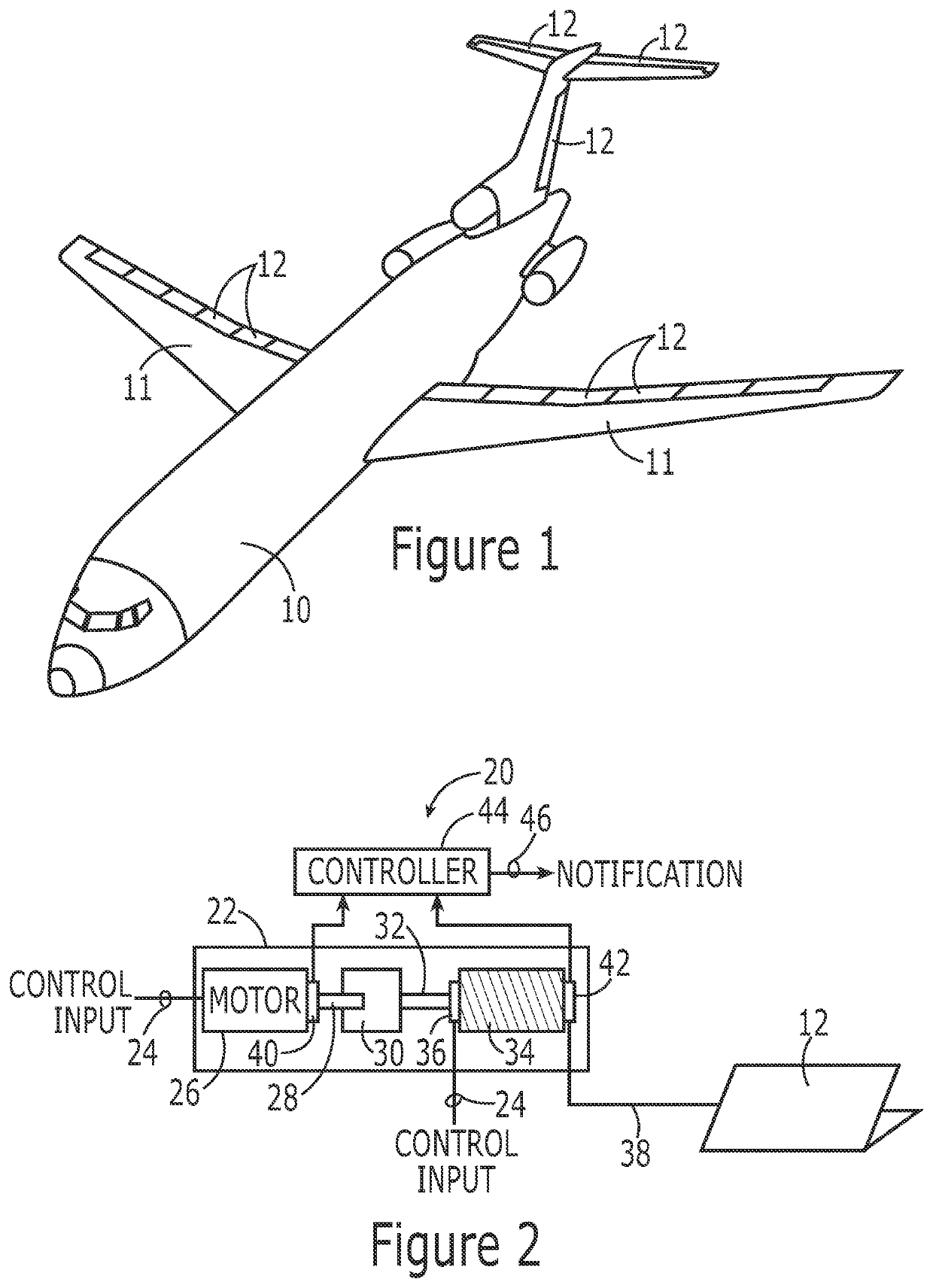
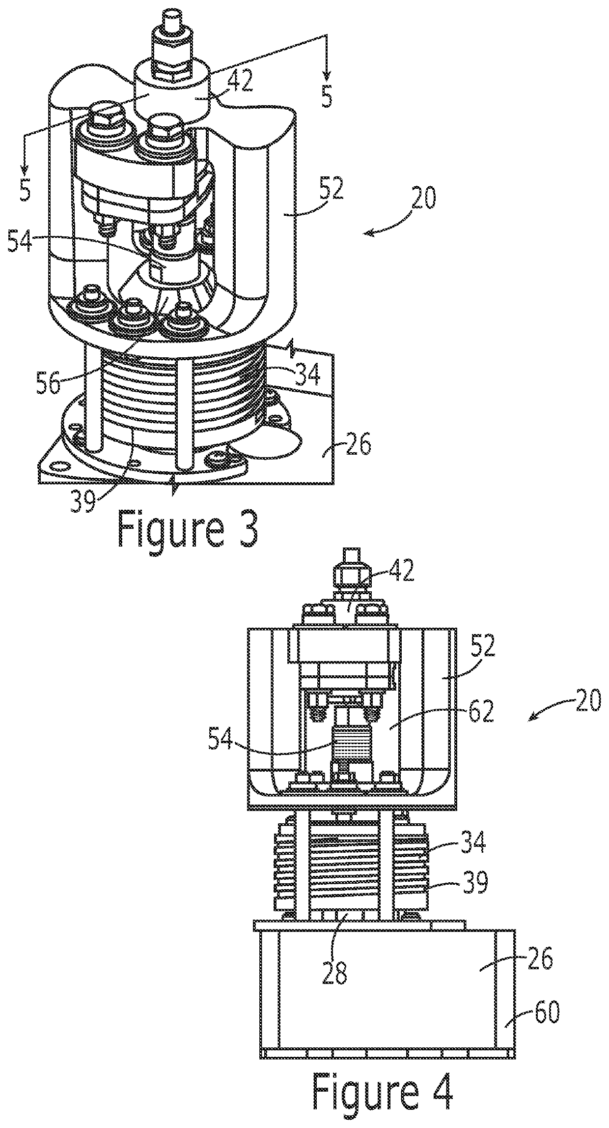
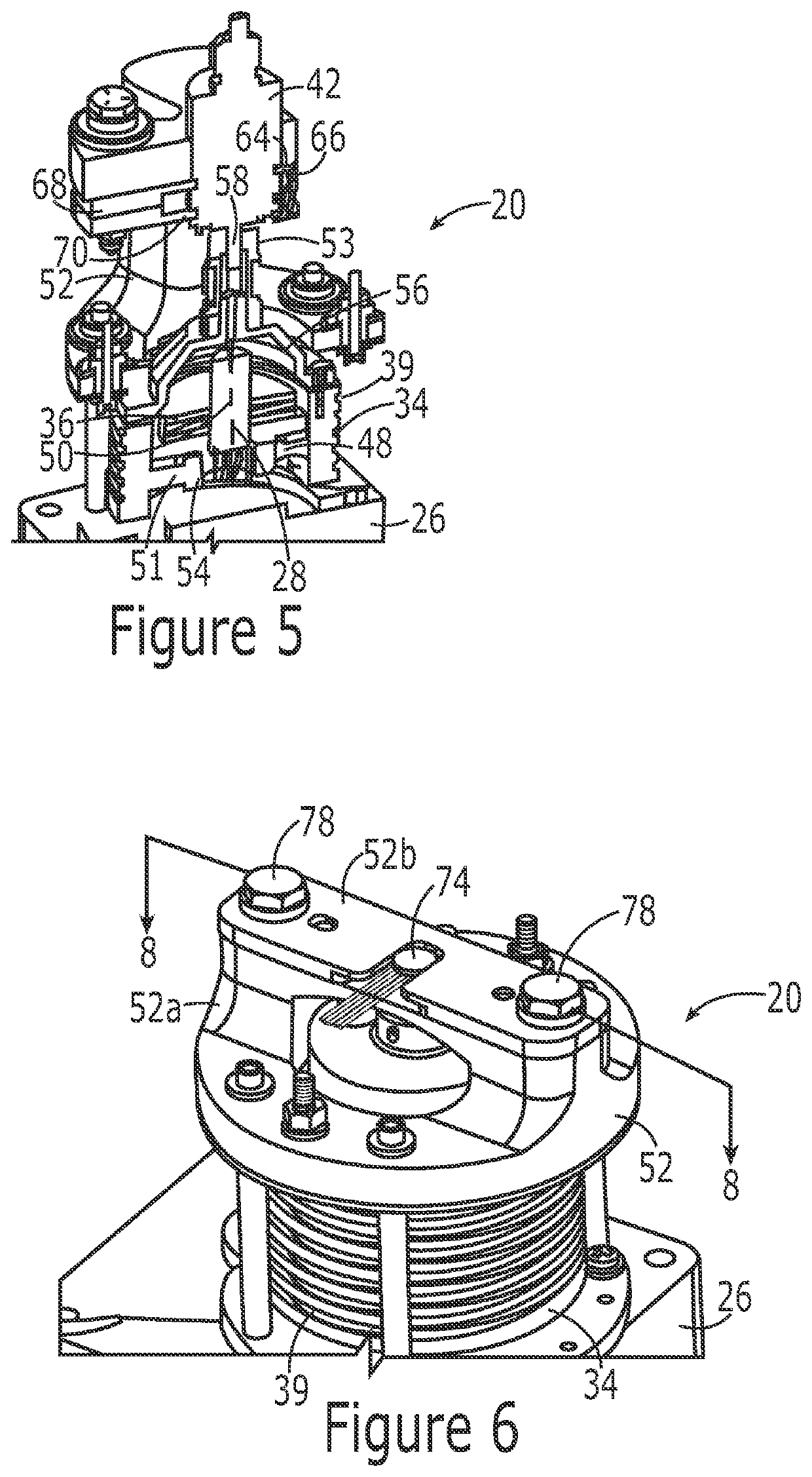

Embodiment Construction

[0025]The present disclosure now will be described more fully hereinafter with reference to the accompanying drawings, in which some, but not all aspects are shown. Indeed, the disclosure may be embodied in many different forms and should not be construed as limited to the aspects set forth herein. Rather, these aspects are provided so that this disclosure will satisfy applicable legal requirements. Like numbers refer to like elements throughout.

[0026]A motor assembly, a control system and a method are provided in order to monitor the rotational relationship of an input shaft associated with a motor and an output shaft, such as a capstan, that collectively serve to controllably actuate a respective control surface. The control system and the associated method can therefore identify an instance in which there is a discrepancy between the rotation of the input shaft associated with the motor and the rotation of the output shaft, such as due to the slippage of a clutch that serves to c...


PUM


Abstract

A motor assembly, control system and associated method monitor the rotational engagement of an input shaft associated with a motor with an output shaft configured to controllably position a control surface. In this regard, a control system includes a motor assembly and an associated controller. The motor assembly includes a motor configured to rotate an input shaft and a first encoder configured to determine a rotational position of the input shaft. The motor assembly also includes an output shaft, such as a capstan, and a second encoder configured to determine a rotational position of the output shaft. The output shaft is rotatably coupled to the input shaft associated with the motor via a clutch. The controller is configured to identify slippage of the clutch based upon information provided by the first and second encoders regarding the rotational positions of the input shaft and the output shaft, respectively.

Description

CROSS-REFERENCE TO RELATED APPLICATIONS[0001]This application claims benefit of U.S. Provisional Application No. 63 / 053,355, filed Jul. 17, 2020, the entire contents of which are incorporated herein by reference.TECHNOLOGICAL FIELD[0002]An example embodiment relates generally to a control system and method to detect clutch slippage and, more particularly, to a control system and method for detecting clutch slippage utilizing encoders.BACKGROUND[0003]A motor may be operatively connected to a control surface in various manners. In some implementations, the motor is connected to a control surface via a cable that is wrapped about a capstan. The motor may include or otherwise be associated with an input shaft that is rotatably coupled to the capstan. Thus, the motor is configured to cause the capstan to controllably rotate and to correspondingly control the extension or retraction of the cable and the associated positioning of the control surface. As such, the pilot of a manually contro...

Claims


Application Information

Patent Timeline
IPC IPC(8): F16D48/06B64C13/50B64F5/60
CPCF16D48/06B64C13/50F16D2500/104F16D2500/30415F16D2500/30406B64F5/60B64C13/30F16D2500/1045F16D2500/30426F16D2500/70426
Inventor PRYOR, THOMAS W.
Owner THE BOEING CO
Learn More