Operation information input apparatus and ultrasonic imaging apparatus

Inactive Publication Date: 2009-08-13
GE MEDICAL SYST GLOBAL TECH CO LLC
View PDF20 Cites 25 Cited by
  • Summary
  • Abstract
  • Description
  • Claims
  • Application Information

AI Technical Summary

Benefits of technology

[0042]In the invention of the seventeenth aspect, the first and second threshold values are changed

Problems solved by technology

According to the background art, however, the frequency of misinputting of operation information by the operator becomes high and the controllability is reduced.
That is, there is a high possibility that since the button images arranged small and in the high density are displayed on the touch panel, an incorrect button image will be selected upon selection of each button image by the operator.
Particularly when the size of one button image is equal to or smaller than the size of a finger tip portion of the operator, plural buttons are simultaneously selected upon the operation of selecting these button images arranged in the high density, thus resulting in further difficulty such as the selection of different butt

Method used


Image

  • Operation information input apparatus and ultrasonic imaging apparatus
  • Operation information input apparatus and ultrasonic imaging apparatus
  • Operation information input apparatus and ultrasonic imaging apparatus

Examples


first embodiment

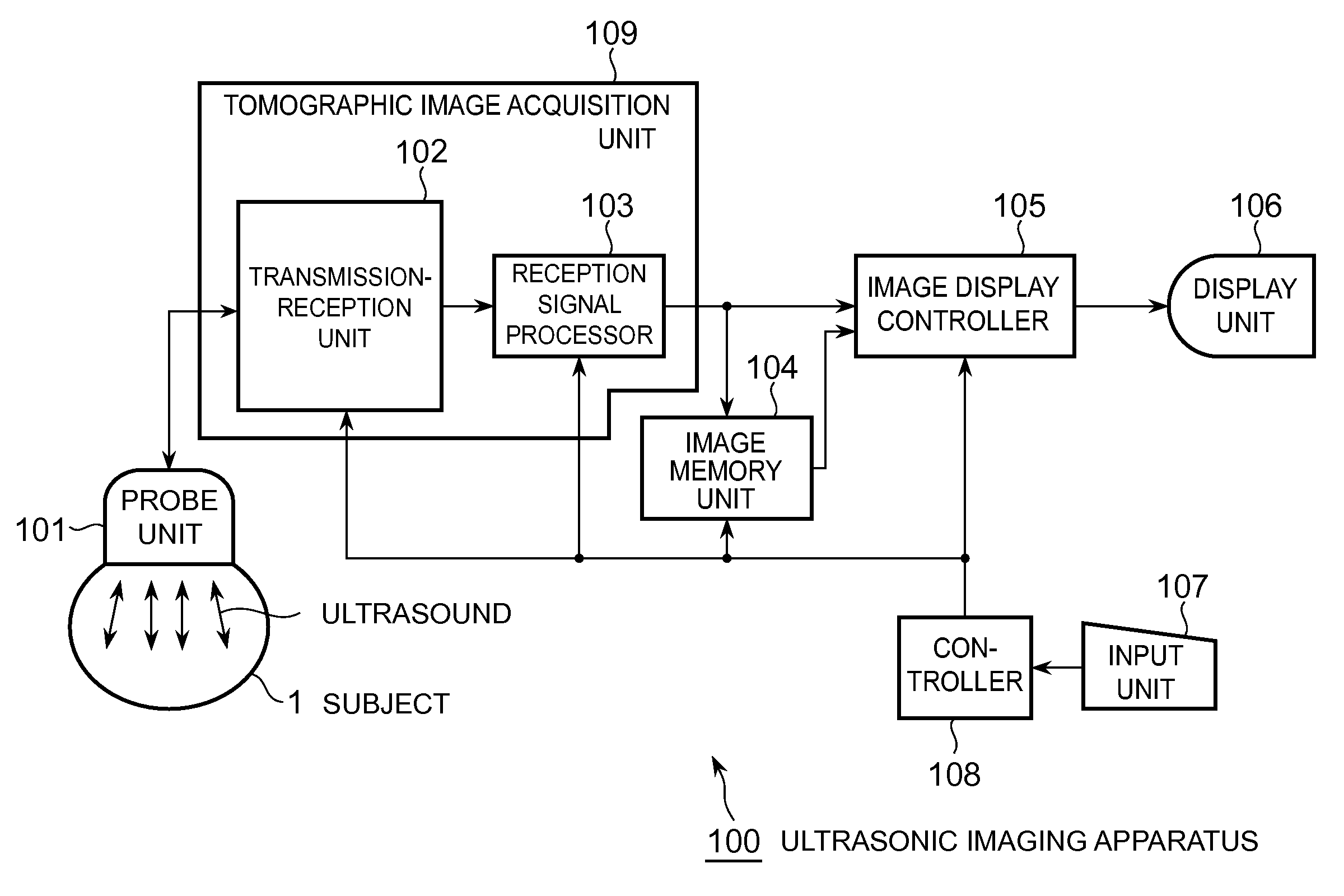
[0067]An overall configuration of an ultrasonic imaging apparatus 100 according to the first embodiment will first be described. FIG. 1 is a block diagram showing the overall configuration of the ultrasonic imaging apparatus 100 according to the first embodiment. The ultrasonic imaging apparatus 100 has a probe unit 101, a tomographic image acquisition unit 109, an image memory unit 104, an image display controller 105, a display unit 106, an input unit 107 and a controller 108. The tomographic image acquisition unit 109 includes a transmission-reception unit 102 and a reception signal processor 103.

[0068]The probe unit 101 applies ultrasound in a specific direction of a portion or region, i.e., a subject 1 for transmitting and receiving the ultrasound and receives ultrasonic signals reflected from inside the subject 1 as time-series sound rays. Concurrently with it, the probe unit 101 performs electronic scanning while the directions to apply the ultrasound are being switched seque...

second embodiment

[0103]On the other hand, although when the position proximal to the touch panel inputted by the operator is not included in the corresponding determination area of each button image, the button array image has been enlarged in the first embodiment, the button array image can also be displayed automatically in enlarged form when the finger tip portion of the operator is approaching the touch panel. With the foregoing in view, a second embodiment will show a case in which a finger tip portion of an operator which is approaching a touch panel is detected and a button array image is displayed in enlarged form in sync with this detection.

[0104]FIG. 8 is a block diagram showing a configuration of an input unit 80 according to the second embodiment. The input unit 80 corresponds to the input unit 107 described in the first embodiment. The second embodiment is exactly the same as the ultrasonic imaging apparatus 100 in other configuration. The input unit 80 includes a first touch panel devi...

third embodiment

[0120]On the other hand, although the approach and contact of each finger tip portion of the operator 2 have been detected using the two touch panels placed in overlaid form in the second embodiment, the magnitudes of detection signals of finger tip portions, which are detected at a non-contact type single touch panel device, are sorted according to plural threshold values, and the approach and contact of each finger tip portion to the touch panel can also be detected. With the foregoing in view, a third embodiment will show a case in which a proximity position detector is provided with a detection signal sorting device to determine the distance of each finger tip portion proximal to the touch panel according to the magnitude of each detection signal, whereby a button array image 35 is displayed in enlarged form and each button image is identified.

[0121]FIG. 11 is a block diagram showing a configuration of an input unit 110 according to the third embodiment. The input unit 110 corre...


PUM


Abstract

An operation information input apparatus includes a button image display device which displays a button array image with a plurality of button images arranged therein, a touch panel device which is overlaid on a display surface of the button image display device and detects proximity position information indicative of each position in the display surface when an operator approaches the display surface, and a push button identifying unit which identifies each button image that the operator has approached, based on the proximity position information and button position information of the button array image.

Description

CROSS REFERENCE TO RELATED APPLICATIONS[0001]This application claims the benefit of Japanese Patent Application No. 2008-028889 filed Feb. 8, 2008, which is hereby incorporated by reference in its entirety.BACKGROUND OF THE INVENTION[0002]The embodiments described herein relate to an operation information input apparatus and an ultrasonic imaging apparatus each of which inputs operation or control information from a touch panel.[0003]A touch panel has recently been used even in an ultrasonic imaging apparatus to input operation or control information therein. The touch panel has no mechanical contact points at the input of the operation information and is long in lifetime and high in reliability.[0004]With greater functionality of the ultrasonic imaging apparatus, the number of operation information inputted manually by an operator is on the increase. With its increase, the required number of button images displayed on the touch panel is also increasing. Adaptations to such an incre...

Claims


Application Information

Patent Timeline
IPC IPC(8): G06F3/041G06F3/048
CPCA61B8/00A61B8/14A61B8/465G06F2203/04806G06F3/044G06F3/04886G06F2203/04108A61B8/467
Inventor HASHIMOTO, HIROSHISAITO, YASUYOAMEMIYA, SHINICHI
Owner GE MEDICAL SYST GLOBAL TECH CO LLC
Why Eureka
Try Eureka