Power tool

a technology of power tools and power cords, applied in the field of power tools, can solve the problems of raising the likelihood, rotors hitting or rubbing against nearby stators, and undesired heating of the operating temperatur

Active Publication Date: 2022-01-27
TECHTRONIC CORDLESS GP
View PDF3 Cites 0 Cited by
  • Summary
  • Abstract
  • Description
  • Claims
  • Application Information

AI Technical Summary

Problems solved by technology

However, tighter air gaps can raise the likelihood that the rotor will strike or rub against the nearby stator if the parts become mis-aligned.
The resulting friction can undesirably raise the operating temperature and create other issues.
But, this arrangement can increase an overall length of the power tool since such motors are typically fully enclosed by two clamshell housing halves that must accommodate the added length of the end caps.
While this arrangement may reduce the overall length of the power tool, it is difficult to mold the plastic housing just right so that the axis of the rotor is aligned with the axis of the stator.

Method used


Image

  • Power tool
  • Power tool
  • Power tool

Examples


Embodiment Construction

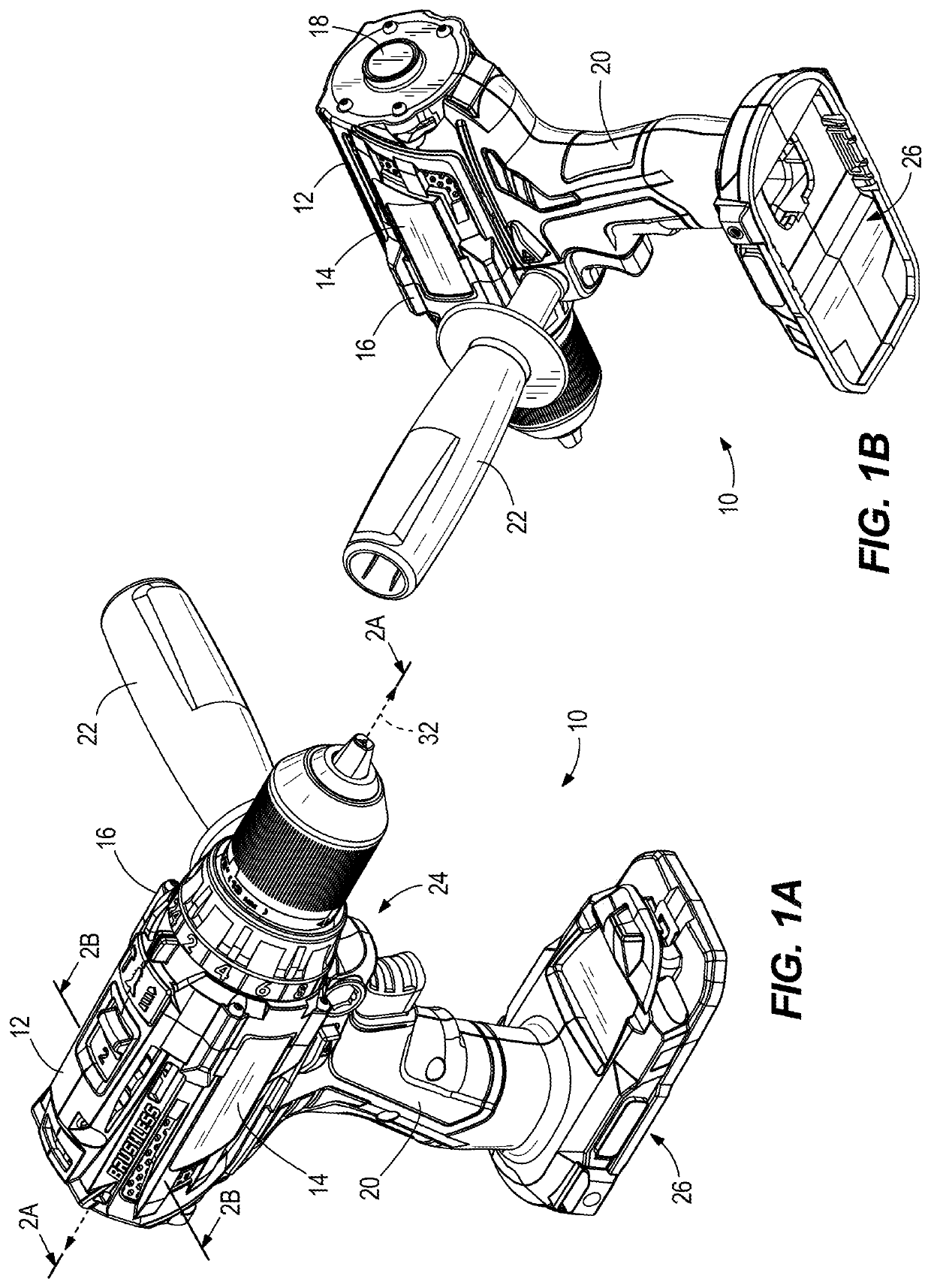
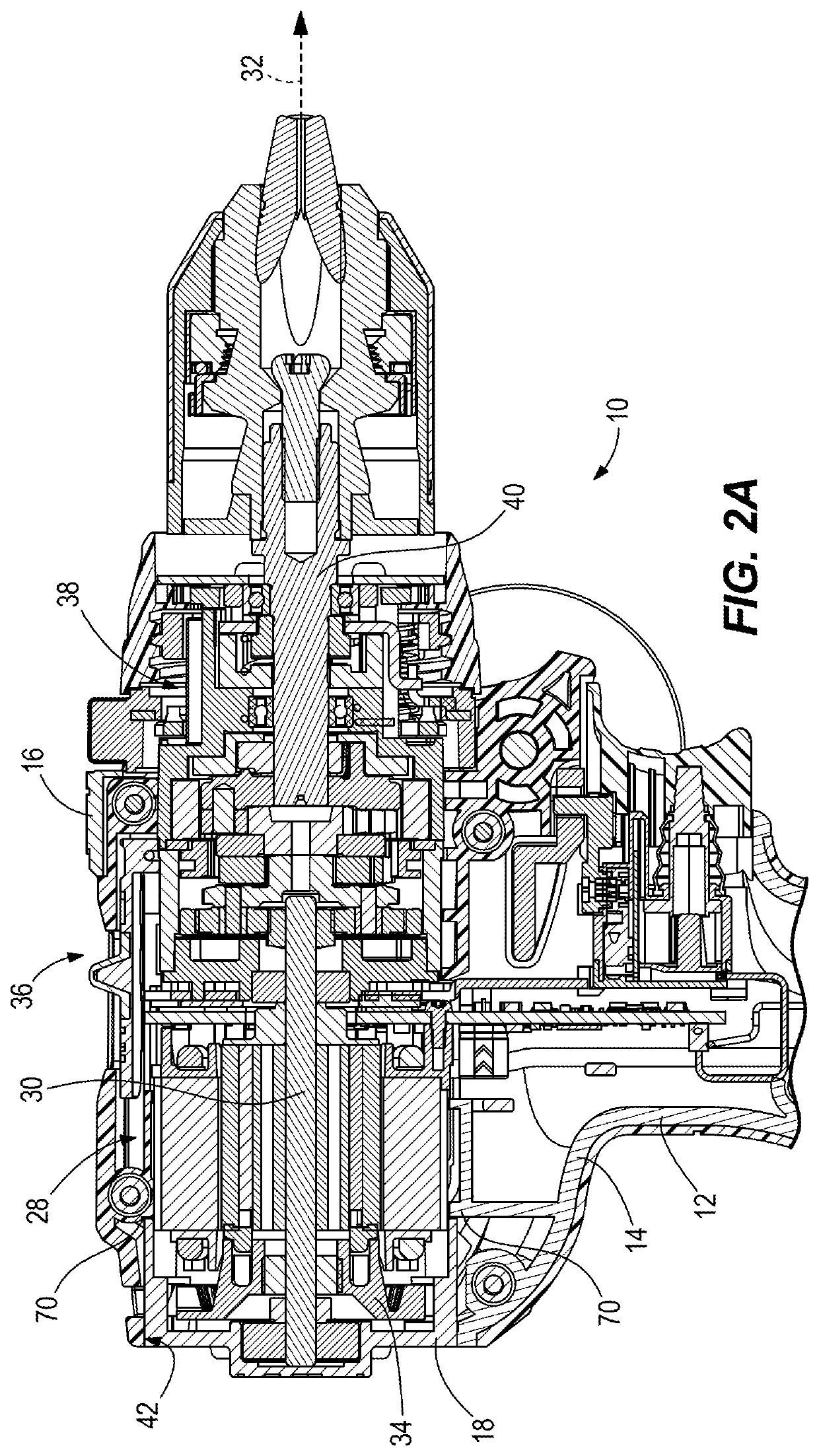
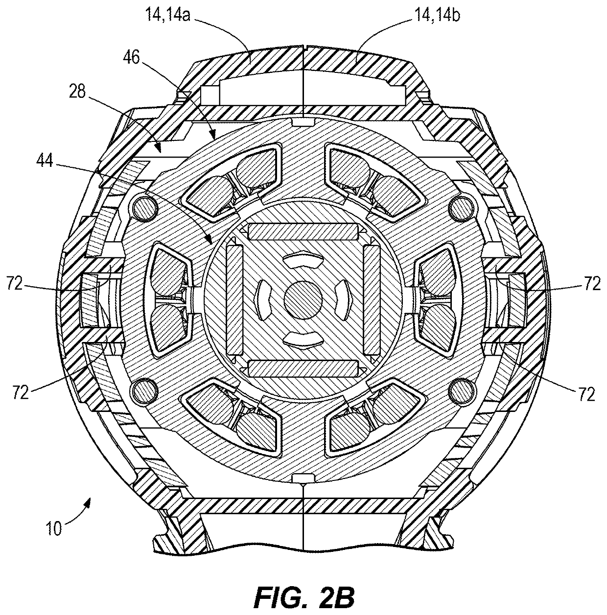
[0019]FIGS. 1A and 1B illustrate a power tool 10 including a housing 12 having a main housing portion 14 formed from, in the illustrated embodiment, clamshell housing halves 14a and 14b (FIG. 2B) that contain therein an electric motor 28 (FIG. 2A). Referring to FIGS. 5A-6B, the motor 28 includes a rotatable rotor assembly 44 surrounded by a stationary stator assembly 46. The rotor assembly 44 is affixed to a rotatable output shaft 30 that, in turn, is rotatably supported at one end by a rear motor bearing 58. The power tool 10 also includes a rear end cap 18 that is directly supported by the stator assembly 46, and also defines a rear bearing pocket 56 that receives and retains the rear motor bearing 58. Thus, as discussed in greater detail below, the rear end cap 18 directly centers the rotor assembly 44 relative to the stator assembly 46, thereby reducing a likelihood that the rotor 44 becomes misaligned with the stator assembly 46 and undesirably strikes the stator assembly 46 du...


PUM


Abstract

A power tool includes a housing and an electric motor supported within the housing. The housing includes a main housing portion that defines a rear opening. The electric motor includes an output shaft supporting a rotor assembly for rotation about a motor axis. The electric motor also includes a stator assembly surrounding the rotor assembly, and a rear end cap. The rear end cap supports a rear motor bearing that rotatably supports the output shaft at a rear end. A portion of the rear end cap resides within the rear opening to close the rear opening.

Description

FIELD OF THE DISCLOSURE[0001]The present disclosure relates to power tools, and more specifically to electric motors for power tools.BACKGROUND OF THE DISCLOSURE[0002]Many power tools, such as drill drivers and hammer drills, include electric motors supported within a tool housing. Such electric motors commonly include a rotor that rotates within a stationary stator, with an air gap separating the rotor and the stator. Typically, the air gap is minimized for magnetic reasons. However, tighter air gaps can raise the likelihood that the rotor will strike or rub against the nearby stator if the parts become mis-aligned. The resulting friction can undesirably raise the operating temperature and create other issues.[0003]To reduce the likelihood that the rotor will strike the stator, many motors employ end caps that are directly supported by the stator, and also support a rotor bearing for rotatably supporting a rotor shaft of the rotor. But, this arrangement can increase an overall leng...

Claims


Application Information

Patent Timeline
Patent Type & Authority Applications(United States)
IPC IPC(8): B25F5/02B25F5/00H02K7/14H02K7/08H02K7/116
CPCB25F5/02B25F5/001B25D16/006H02K7/08H02K7/116H02K7/145B25D17/04B25D2216/0084B25D2250/121
Inventor BENZING, GLENN L.
Owner TECHTRONIC CORDLESS GP
Why Eureka
Try Eureka