Method and apparatus to determine rotational position of an electrical machine

a technology of rotational position and electrical machine, which is applied in the direction of program control, external condition input parameters, gas pressure propulsion mounting, etc., can solve the problems of difficult control of mechanical alignment, direct influence of measurement accuracy, and error-prone position of resolver relative to machine rotor

Active Publication Date: 2008-11-06
GM GLOBAL TECH OPERATIONS LLC
View PDF99 Cites 189 Cited by
  • Summary
  • Abstract
  • Description
  • Claims
  • Application Information

AI Technical Summary

Benefits of technology

[0009]It is therefore an object of this invention to provide a control system for an electric machine which precisely and accurately determines position of a rotor device relative to a stator for the electrical machine, especially one comprising a synchronous multipole electrical machine, including one for application on a fuel / electric hybrid powertrain for a vehicle.

Problems solved by technology

Position of the resolver relative to the machine rotor is subject to error due to factors including manufacturing variations and tolerances.
Also, the accuracy of this position measurement is critical, as it will affect the performance of the motor control, most noticeably in torque production and linearity.
However, the accuracy of the measurement is directly affected by the initial alignment of the resolver during installation.
The installation of the resolver and mechanical alignment can be difficult to control in production.

Method used


Image

  • Method and apparatus to determine rotational position of an electrical machine
  • Method and apparatus to determine rotational position of an electrical machine
  • Method and apparatus to determine rotational position of an electrical machine

Examples


Embodiment Construction

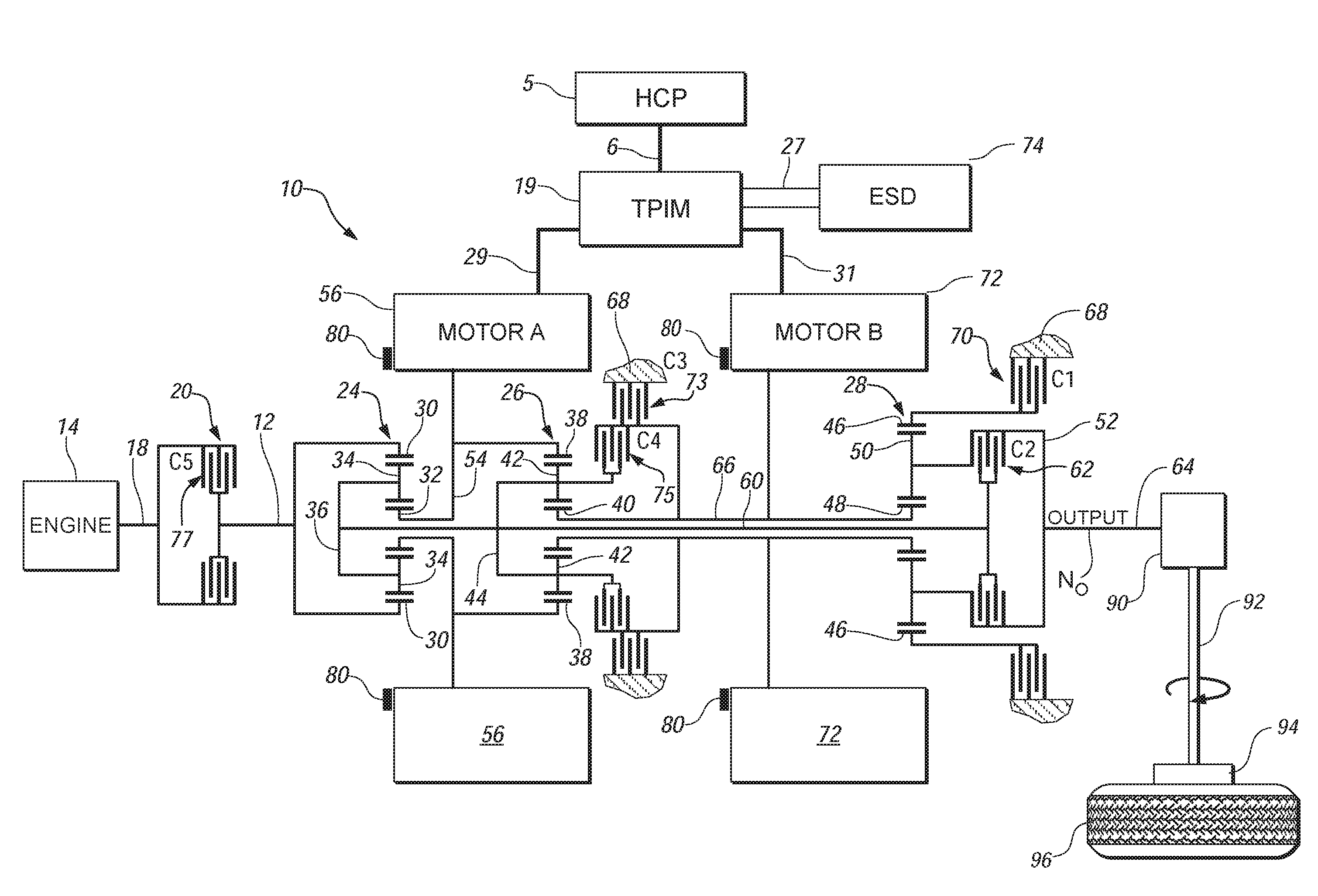
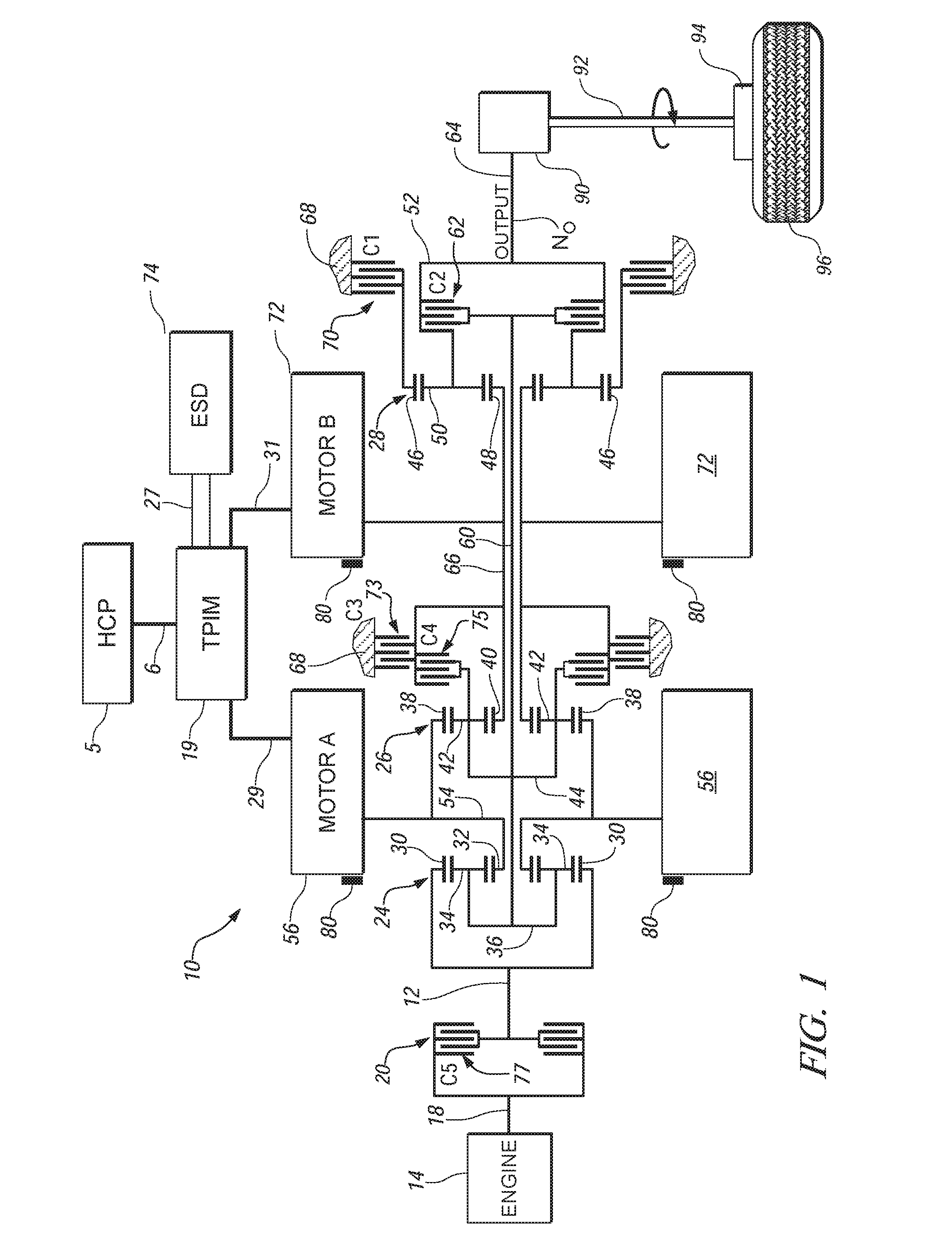
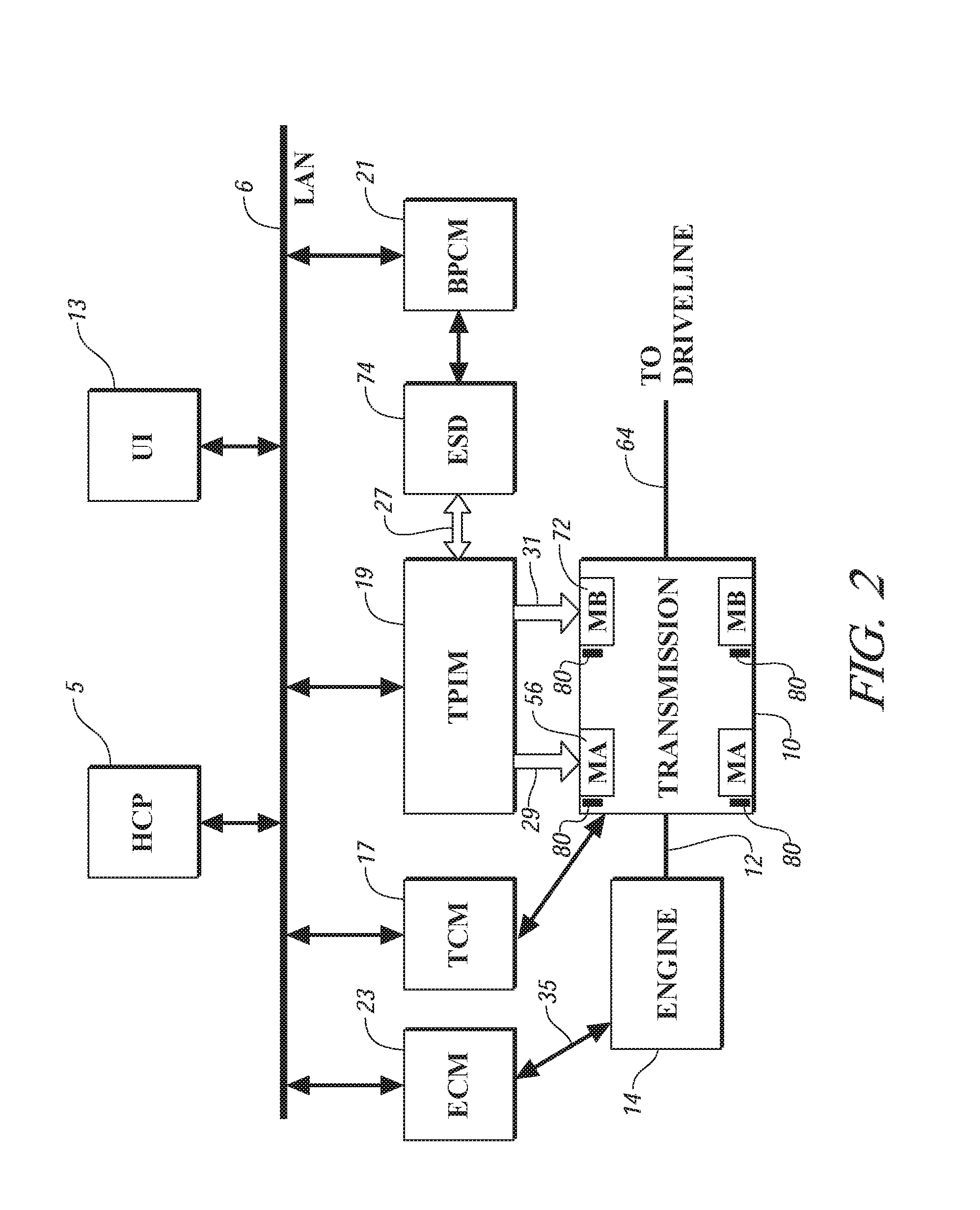
[0019]Referring now to the drawings, wherein the showings are for the purpose of illustrating the invention only and not for the purpose of limiting the same, FIGS. 1 and 2 depict a system comprising an engine 14, transmission 10, control system, and driveline which has been constructed in accordance with an embodiment of the present invention.

[0020]Mechanical aspects of exemplary transmission 10 are disclosed in detail in commonly assigned U.S. Pat. No. 6,953,409 entitled TWO-MODE, COMPOUND-SPLIT, HYBRID ELECTRO-MECHANICAL TRANSMISSION HAVING FOUR FIXED RATIOS, which is incorporated herein by reference. The exemplary two-mode, compound-split, electro-mechanical transmission embodying the concepts of the present invention is depicted in FIG. 1, and is designated generally by the numeral 10. The transmission 10 has an input shaft 12 preferably directly driven by an engine 14. A transient torque damper 20 is incorporated between the output shaft 18 of the engine 14 and the input membe...


PUM


Abstract

A control system and method to determine position of a rotor relative to a stator for a synchronous multipole electrical machine is presented, including one for application on a fuel/electric hybrid powertrain for a vehicle. The machine includes a stator, a rotor, and a rotor position sensing mechanism. The control system controls the electrical machine, in conjunction with an electrical storage device and an inverter, using algorithms and calibrations which derive a rotor position based upon a sensorless position sensing technique, and determine an offset from a sensed rotor position. Electrical output from the inverter to the machine is controlled based the offset, which is stored non-volatile memory. A rotor position is derived based upon a sensorless position sensing technique during initial machine operation after startup of the machine, and includes operation in a torque-generative mode and in an electrical energy-generative mode.

Description

TECHNICAL FIELD[0001]This invention pertains generally to control of an electrical machine, and more specifically to a control system for an electric machine to determine rotational position to optimize energy usage to supply motive torque in a vehicle propulsion system.BACKGROUND OF THE INVENTION[0002]Control systems for electrical motors typically include a feedback device such as a position sensor to provide data to measure position and rotational velocity of the motor. On a three-phase multipole synchronous electrical motor, precise and accurate measurement of position of a rotor relative to each of the poles of a stator is important to achieve efficient transmission of electrical energy. Rotor position is typically measured using the position sensor to determine position of the resolver. Position of the resolver relative to the machine rotor is subject to error due to factors including manufacturing variations and tolerances. Electrical motor manufacturers have attempted to cor...

Claims


Application Information

Patent Timeline
Patent Type & Authority Applications(United States)
IPC IPC(8): H02P5/00B60K6/26G05B1/06G05B11/06G05B19/02
CPCB60K1/02Y02T10/643B60K6/365B60K6/445B60K6/547B60L2240/421B60L2240/441B60L2240/486B60W10/02B60W10/06B60W10/08B60W20/00B60W2510/0638B60W2510/081B60W2510/104B60W2540/10B60W2540/12B60W2540/16B60W2550/12B60W2710/027B60W2710/0666F16H2037/0866F16H2037/102F16H2037/104F16H2037/106H02P21/146Y02T10/6286Y02T10/6239B60K6/26H02P21/18B60W2555/20Y02T10/64Y02T10/62B60W2510/08B60W20/15
Inventor GLEASON, SEAN E.SCHULZ, STEVEN E.PRIHODA, PATRICK M.
Owner GM GLOBAL TECH OPERATIONS LLC
Why Eureka
Try Eureka