
Method for dynamically determining peak output torque in an electrically variable transmission

a technology of electrically variable transmission and peak output torque, which is applied in the direction of electric vehicles, propulsion parts, engine-driven generators, etc., can solve the problems of inability to adapt to real-time, dynamic, multi-variable solutions for effective control, and general steady-state operation

Active Publication Date: 2005-11-17
GM GLOBAL TECH OPERATIONS LLC
View PDF5 Cites 191 Cited by
  • Summary
  • Abstract
  • Description
  • Claims
  • Application Information

AI Technical Summary

Benefits of technology

The patent text describes a method for determining the output torque limits of a powertrain that includes an engine and an electrically variable transmission. The method involves determining the feasible motor torque operating space and input torque limits within that space. The input torque limits are determined based on the engine torque limits and motor torque limits. The motor torque limits are determined based on the input torque limits and the least constrained output torques. The engine torque limits are determined based on the engine operating parameters, while the motor torque limits are determined based on the motor operating parameters. The technical effect of this invention is to provide a more efficient and effective powertrain for vehicles that can optimize torque output and improve overall performance.

Problems solved by technology

Such limitations include, for example, available engine torque, available electric machine torque and the available electrical energy storage system power.
But such techniques are generally limited to steady state operation, neglecting the significance of inertia torques upon the powertrain from vehicle dynamic conditions including vehicular and powertrain (engine and electric machine) accelerations.
Such techniques, therefore, are ill equipped for adaptation to real-time, on-vehicle, dynamic, multi-variable solutions for effective control.

Method used


Image

  • Method for dynamically determining peak output torque in an electrically variable transmission
  • Method for dynamically determining peak output torque in an electrically variable transmission
  • Method for dynamically determining peak output torque in an electrically variable transmission

Examples


Embodiment Construction

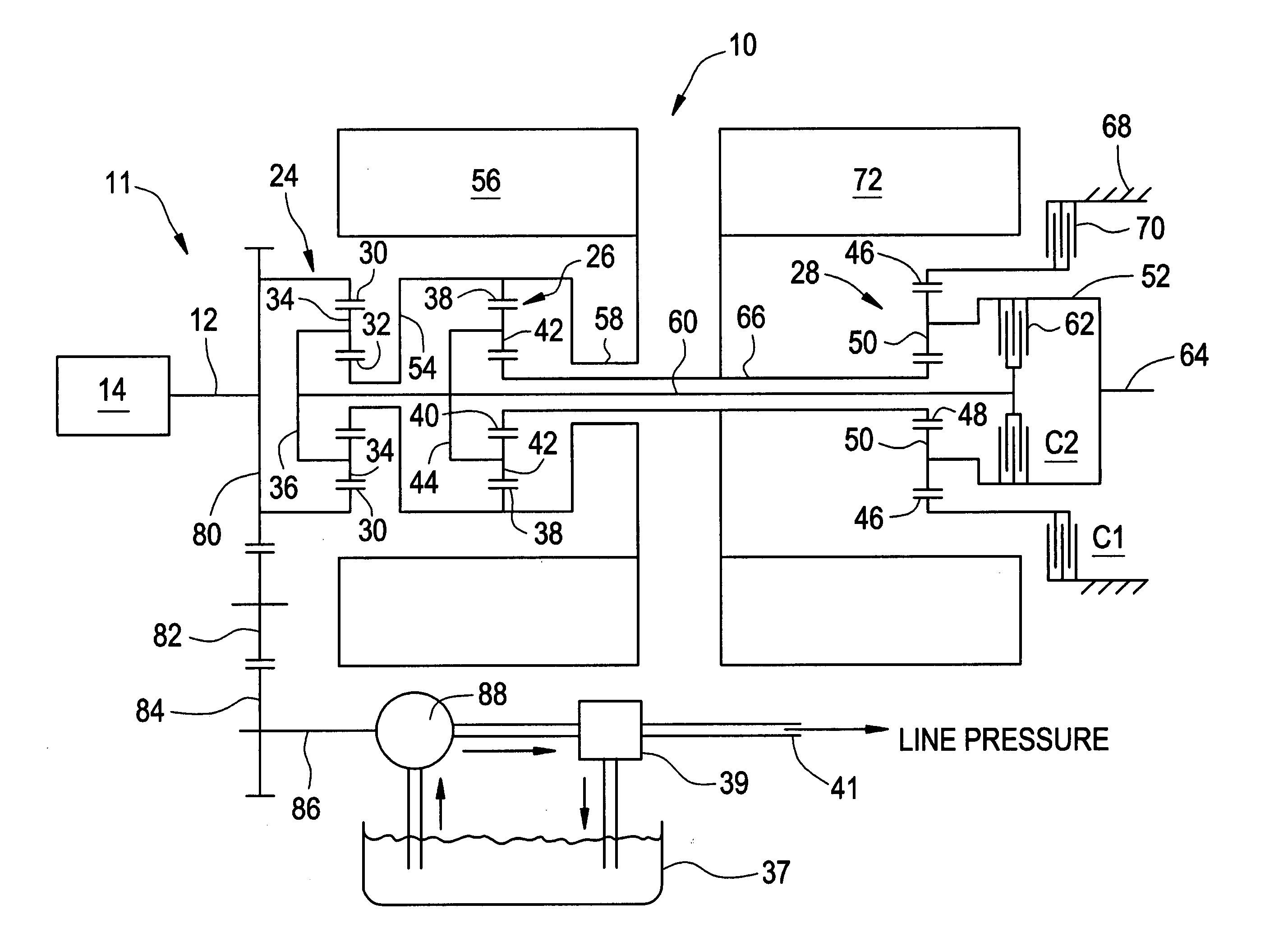
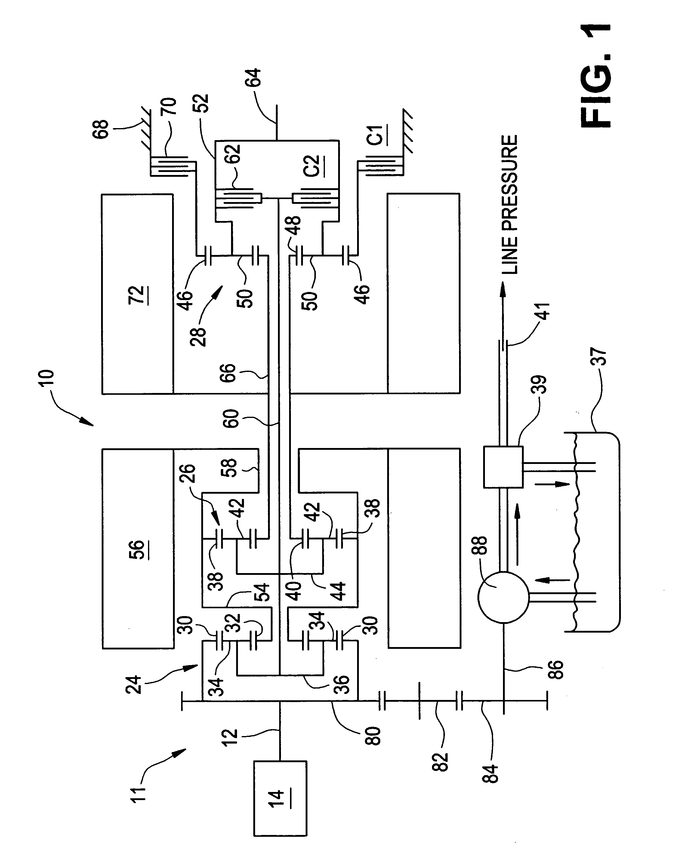
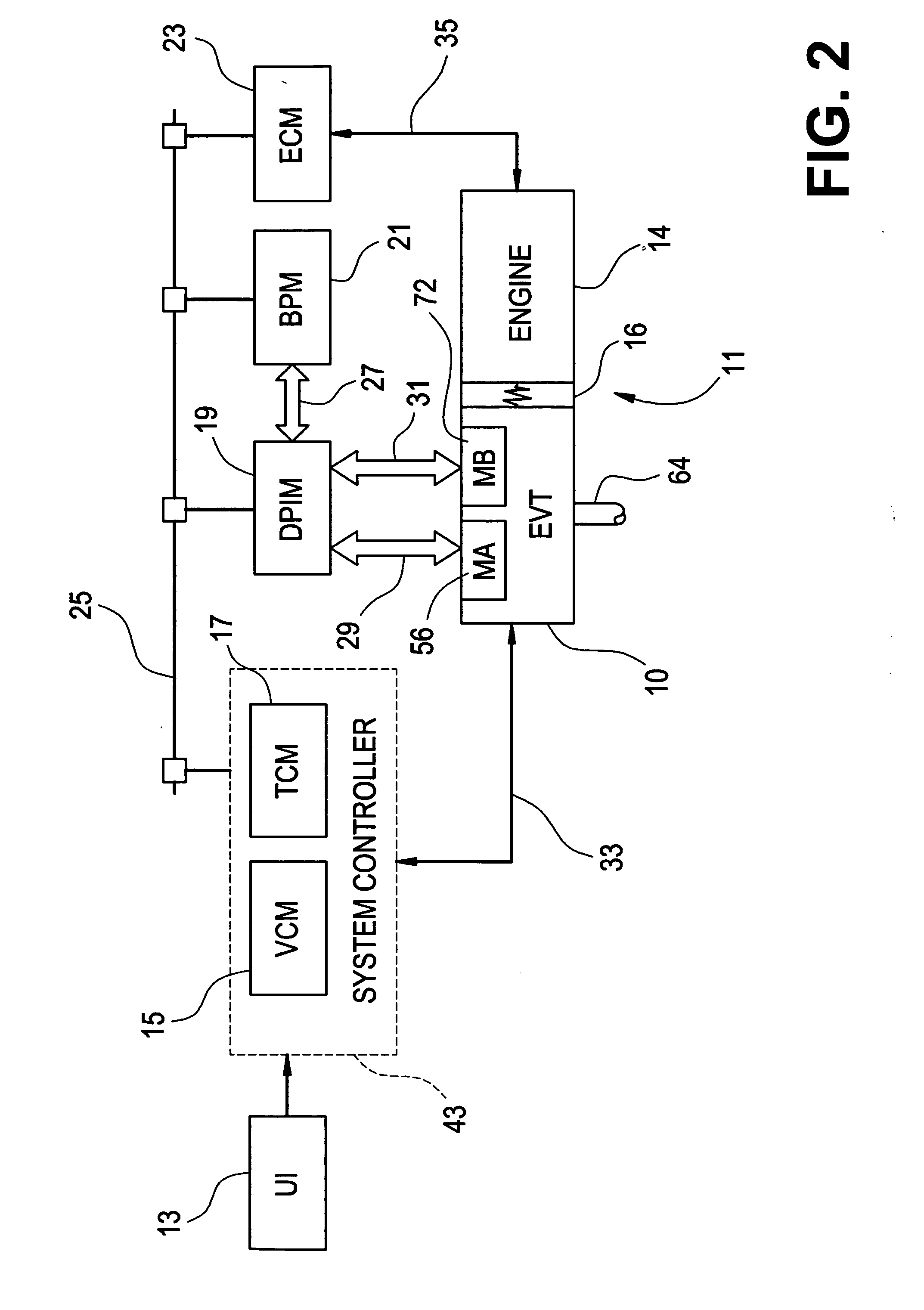
[0024] With reference first to FIGS. 1 and 2, a vehicular powertrain system is generally designated 11. Included in the powertrain 11 is one representative form of a multi-mode, compound-split, electrically variable transmission (EVT) particularly suited for implementing the controls of the present invention and designated generally by the numeral 10 in FIGS. 1 and 2. With particular reference, then, to those figures, the EVT 10 has an input member 12 that may be in the nature of a shaft which may be directly driven by an engine 14 or, as shown in FIG. 2, a transient torque damper 16 may be incorporated between the output member of the engine 14 and the input member of the EVT 10. The transient torque damper 16 may incorporate, or be employed in conjunction with, a torque transfer device (not shown) to permit selective engagement of the engine 14 with the EVT 10, but it must be understood that such a torque transfer device is not utilized to change, or control, the mode in which the...


PUM


Abstract

A method for determining output torque limits of a powertrain including an electrically variable transmission relies upon a model of the electrically variable transmission. Transmission operating space is defined by combined electric machine torque constraints and engine torque constraints. Output torque limits are determined at the limits of the transmission operating space.

Description

CROSS REFERENCE TO RELATED APPLICATIONS [0001] This application claims priority to U.S. Provisional Ser. No. 60 / 571,658 filed on May 15, 2004, which is hereby incorporated herein by reference in its entirety.TECHNICAL FIELD [0002] The present invention is related to control of a vehicular powertrain. More particularly, the invention is concerned with real-time, on-vehicle determinations of output torque limitations of an electrically variable transmission. BACKGROUND OF THE INVENTION [0003] Various hybrid powertrain architectures are known for managing the input and output torques of various prime-movers in hybrid vehicles, most commonly internal combustion engines and electric machines. Series hybrid architectures are generally characterized by an internal combustion engine driving an electric generator which in turn provides electrical power to an electric drivetrain and to a battery pack. The internal combustion engine in a series hybrid is not directly mechanically coupled to th...

Claims


Application Information

Patent Timeline
Patent Type & Authority Applications(United States)
IPC IPC(8): B60W10/06G01M99/00B60W10/08B60W20/00B60W30/18F16H3/72
CPCB60K6/445Y10T477/23B60L11/14B60L2240/423B60W10/06B60W10/08B60W20/00B60W30/184B60W2710/0666B60W2710/083F16H3/728F16H2037/0866F16H2037/102F16H2037/104F16H2200/201Y02T10/6217Y02T10/6286Y02T10/7077Y02T10/642Y02T10/6239B60L11/123B60L50/61B60L50/16Y02T10/62Y02T10/64Y02T10/7072Y02T10/70B60W20/30
Inventor HUBBARD, GREGORY A.HSIEH, TUNG-MINGHEAP, ANTHONY H.
Owner GM GLOBAL TECH OPERATIONS LLC
Learn More