Roller shutter lock assembly

a technology of roller shutters and locking bars, which is applied in the direction of building locks, shutters/movable grilles, constructions, etc., can solve the problems of reducing the noise created by the shutter assembly, affecting the operation of the slats/shutter curtain, and the type of locking bars described

Pending Publication Date: 2022-02-03
CW PRODS
View PDF13 Cites 0 Cited by
  • Summary
  • Abstract
  • Description
  • Claims
  • Application Information

AI Technical Summary

Benefits of technology

The patent text describes a mechanism that stops the bolt from moving too far within its carriage. This helps to improve the performance of the mechanism.

Problems solved by technology

This may occur for example when a leveraging bar is placed underneath a bottom rail of a closed shutter and excessive force applied downwardly on the leveraging bar.
One of the problems with the use of a keyed locking bar in the bottom rail or / is that it needs to be manually actuated by rotation of either a suitable handle mechanism or rotation of a key in a lock assembly.
Having a handle mechanism on window slats is generally seen as aesthetically unpleasing and also provides hinderance to the operation of the slats / shutter curtain as it prohibits the complete opening of the curtain into a fully retracted or open position due to the projecting handle abutting against the uppermost portion of the window frame.
Another problem with keyed locking bars is that in order to be operated a key has to be inserted and rotated in the lock requiring a user to ensure that they have ready access to the required keys in order to lock the roller shutter as well as open it.
Typically locking bars of the type described also increase the noise created by the shutter assembly as it opens and closes due to the locking bar rattling within the bottom rail.

Method used


Image

  • Roller shutter lock assembly
  • Roller shutter lock assembly
  • Roller shutter lock assembly

Examples


Embodiment Construction

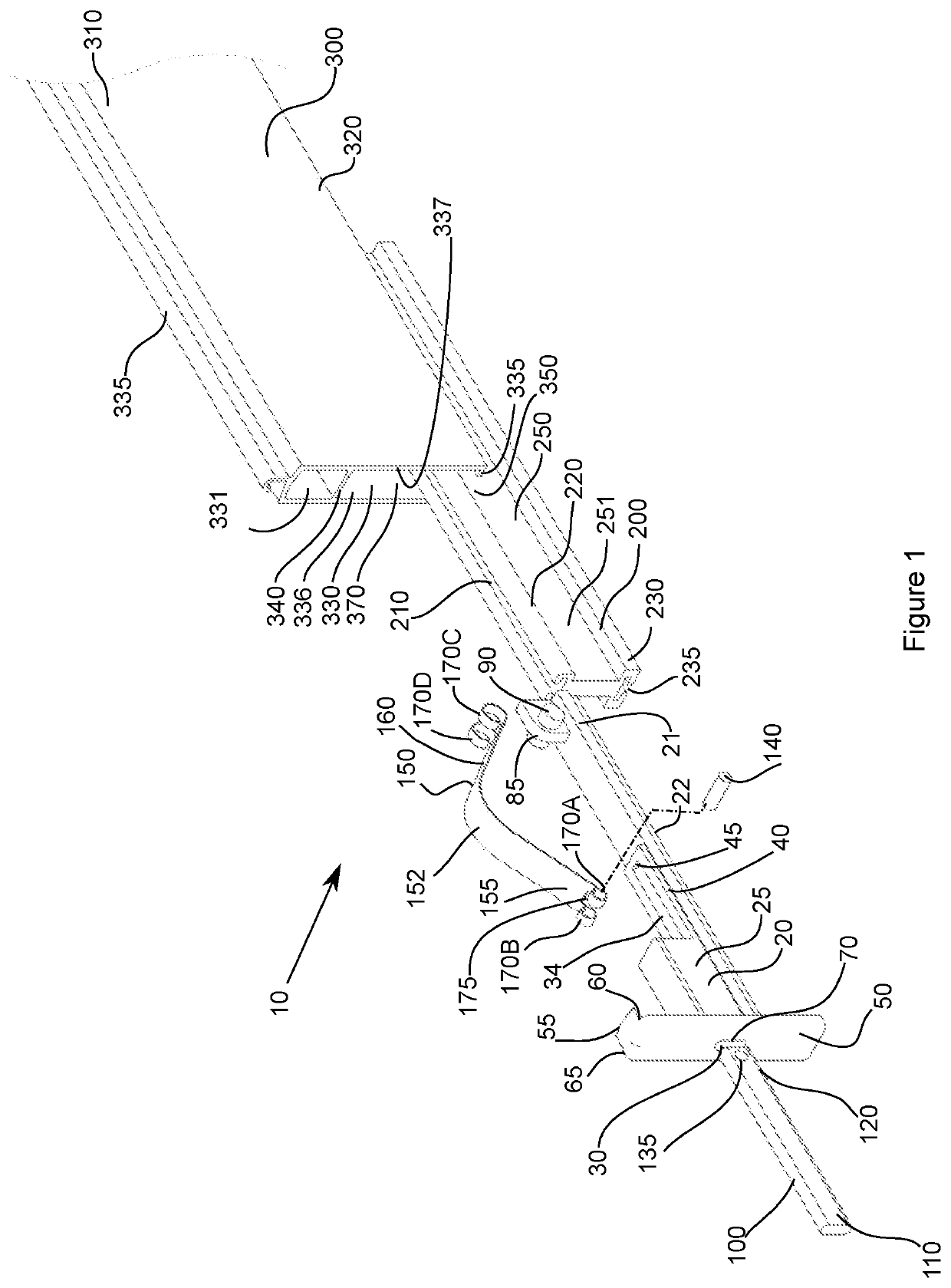
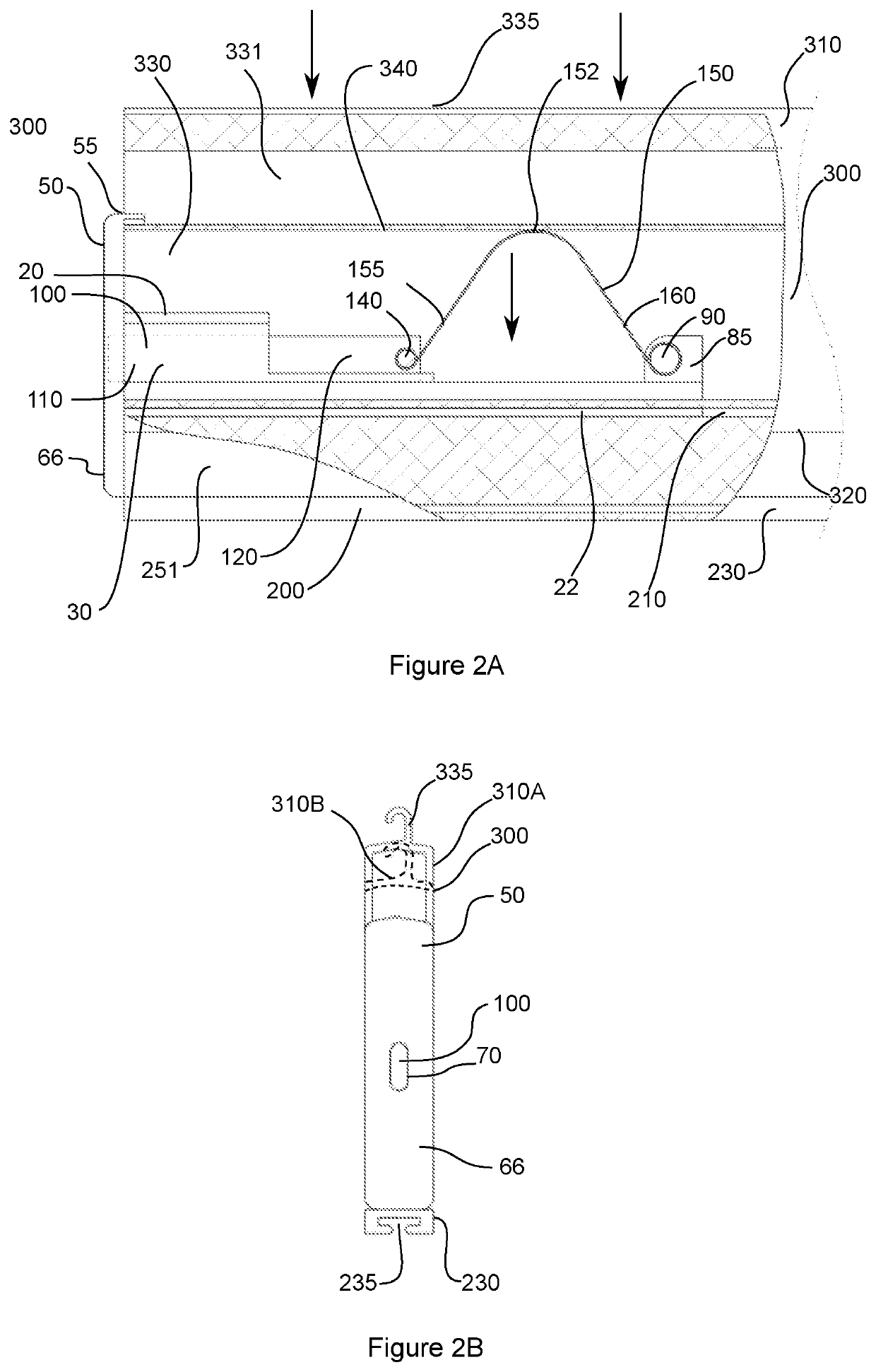
[0049]With reference to FIG. 1, the shutter blocking assembly 10 includes a lock carriage 20 having a sleeve section 25 that includes a bore 30 extending through. A channel or groove 34 extends along the rear portion 40 which includes a back stop 45. An endcap 50 is opposite to the rear portion 40 and may be integrated with the carriage 20 or separately affixed. The endcap 50 includes a tab portion 55 with indented sides 60 and 65 respectively and an opening 70 on face 66. A locking bolt or bar 100 has a front end 110 and a rear end 120, the rear end 120 including an opening 135 which is transverse to the longitudinal length of the locking bolt. The outer peripheral shape of the locking bolt 100 is shaped to fit within the opening 70 of the endcap 50 and thus into the bore 30 of the sleeve section 25. The rear end 120 of the locking bolt 100 then can slide along the groove 34 of the rear portion 40 and when fully inserted the rear face of the rear end 120 abuts the stop 45 and the f...


PUM


Abstract

A shutter locking assembly that has a bolt carriage with a bolt slidingly engageable with the bolt carriage and a biasing (actuator) means operatively connected to the bolt member and the bolt carriage. The bolt carriage is inserted into a cavity of a shutter slat, and the action of moving the shutter slat between an up (open) position and a down (locked) position, causing the bolt to be moved between an extended position and a retracted position. When the shutter slat is in a down (locked) position the bolt engages with a bolt receiving opening adjacent to the shutter slat, and when in an up (open position) the bolt is retracted

Description

FIELD OF THE INVENTION[0001]The present invention relates to a locking arrangement for securing a plurality of pivotally connected slats forming a roller shutter.[0002]In particular, the present invention relates to a locking means for a roller shutter into a preset position or location by way of locking engagement to a side rail / guide rail.BACKGROUND[0003]Roller shutters use a curtain of interconnected slats that typically travel in a pair of opposing side guide rail or guide tracks. The formed curtain is arranged so as to move between an open rolled up position and a lowered closed rolled down position which may be undertaken either by manual movement of the shutters or alternatively by using a motor to drive a shaft onto which the curtain of interconnected slats is wound around. Roller shutters are commonly used as they provide strength and security in both industrial and commercial buildings as well as in residential buildings.[0004]Roller shutters can be easily actuated to move...

Claims


Application Information

Patent Timeline
Patent Type & Authority Applications(United States)
IPC IPC(8): E06B9/86E05B15/10E05B65/00
CPCE06B9/86E06B2009/802E05B65/0021E05B15/101E06B9/90E06B9/15E05C1/004E05C19/028E05C19/06E06B2009/1572E06B2009/801E05Y2600/46E05Y2600/41E05Y2201/48E06B9/80E06B2009/804E06B2009/805E05B2015/0458E05C1/08
Inventor ELASSAAD, IBRAHIM
Owner CW PRODS
Why Eureka
Try Eureka