Wind power generation apparatus

a wind power generation and wind power technology, applied in the direction of wind motors, wind motor control, motors, etc., can solve the problems of only applying electronic braking mechanisms, damage to inner components, and cannot be applied to the conventional wind power generation apparatus operated in continuously high speed winds. achieve the effect of improving the problem

Active Publication Date: 2022-02-03
HERO POWER TECH CORP
View PDF2 Cites 1 Cited by
  • Summary
  • Abstract
  • Description
  • Claims
  • Application Information

AI Technical Summary

Benefits of technology

[0005]In response to the above-referenced technical inadequacies, the present disclosure provides a wind power generation apparatus to effectively improve on the issues associated with conventional wind power generation apparatuses.
[0008]Therefore, the wind power generation apparatus of the present disclosure uses the acceleration restriction mechanism arranged therein to generate an eddy current in the metal ring for reducing the rotating acceleration of the rotor assembly, so that the wind power generation apparatus can be operated in continuously high speed winds.

Problems solved by technology

When the conventional wind power generation apparatus is operated in high speed winds, the high speed winds may drive the conventional wind power generation apparatus to have a high rotating acceleration that rapidly increases a rotating speed of the blades, which results in damage to inner components thereof.
However, the electronic braking mechanism is only applied to the conventional wind power generation apparatus operated in sudden high speed winds, but cannot be applied to the conventional wind power generation apparatus operated in continuously high speed winds.

Method used


Image

  • Wind power generation apparatus
  • Wind power generation apparatus
  • Wind power generation apparatus

Examples


first embodiment

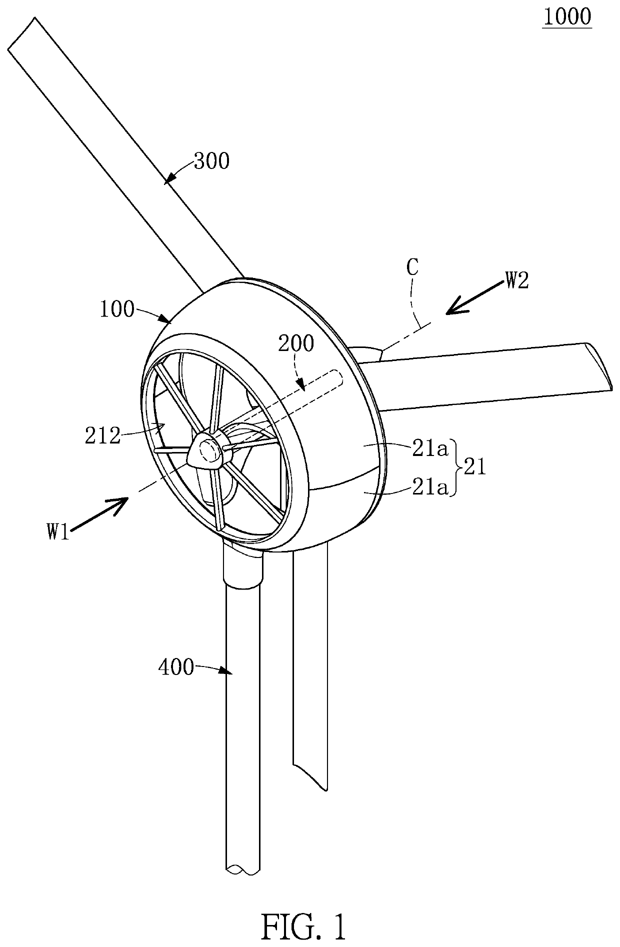
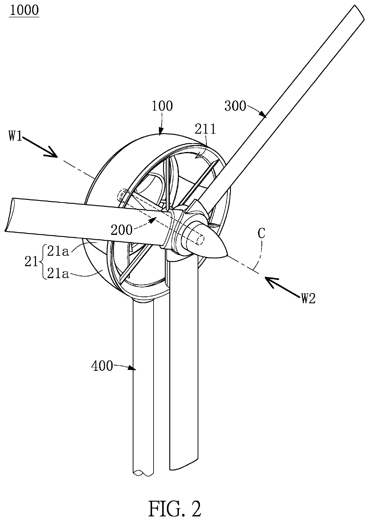
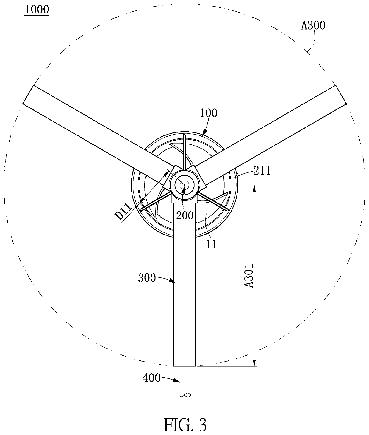
[0029]Referring to FIG. 1 to FIG. 13, a first embodiment of the present disclosure provides a wind power generation apparatus 1000. The wind power generation apparatus 1000 can be horizontal axis type wind power generation equipment, but the present disclosure is not limited thereto. Moreover, the structural design of the wind power generation apparatus 1000 in the present embodiment is different from that of a water electricity generation apparatus, so that no water electricity generation apparatus can provide any motivation to the structural design of the present embodiment.

[0030]As shown in FIG. 1 to FIG. 4, the wind power generation apparatus 1000 includes a rotating shaft 200, a lift blade set 300 fixed on the rotating shaft 200, a wind power generation device 100 assembled to the rotating shaft 200, a supporting stand 400 connected to the wind power generation device 100, and an acceleration restriction mechanism 500 that is in cooperation with the wind power generation device...

second embodiment

[0063]Referring to FIG. 14, a second embodiment of the present disclosure is similar to the first embodiment of the present disclosure, so that descriptions of the same components in the first and second embodiments of the present disclosure will be omitted for the sake of brevity, and the following description only discloses different features between the first and second embodiments (e.g., connections between the elastic members 530 and the corresponding components of the present embodiment are different from that of the first embodiment).

[0064]Specifically, in the present embodiment, one end of each of the elastic members 530 is connected to the inner housing 12, and another end of each of the elastic members 530 is connected to a portion (e.g., the second end portion 5114) of one of the swing structures 510 arranged adjacent to the magnetic portion 5112.

third embodiment

[0065]Referring to FIG. 15, a third embodiment of the present disclosure is similar to the first embodiment of the present disclosure, so that descriptions of the same components in the first and third embodiments of the present disclosure will be omitted for the sake of brevity, and the following description only discloses different features between the first and third embodiments (e.g., the acceleration restriction mechanism 500 in the present embodiment includes a plurality of torsion springs 550 respectively assembled to the swing structures 510 and used to replace the elastic members 530 of the first embodiment).

[0066]Specifically, in the present embodiment, each of the swing arms 511 is assembled with one of the torsion springs 550. Each of the torsion springs 550 includes an elastic portion 551, a first positioning portion 552, and a second positioning portion 553, the latter two of which respectively extend from two ends of the elastic portion 551. Moreover, in each of the s...


PUM


Abstract

A wind power generation apparatus includes a rotating shaft, a wind power generation device assembled to the rotating shaft, and an acceleration restriction mechanism. The wind power generation device includes a drag blade fixed on the rotating shaft, an inner housing connected to an outer edge of the drag blade, and an outer housing sleeved around the inner housing. The acceleration restriction mechanism includes a plurality of swing arms pivotally connected to the inner housing and a metal ring fixed on the outer housing. A magnetic portion of each swing arm is movable relative to the inner housing from an initial position to an acceleration restriction position. When the magnetic portion of each swing arm is at the acceleration restriction position, the magnetic portion at least partially covers the metal ring, so that the metal ring generates an eddy current limiting a rotating acceleration of the drag blade.

Description

CROSS-REFERENCE TO RELATED PATENT APPLICATION[0001]The present application is the U.S. national stage of International Application PCT / IB2019 / 061262, filed Dec. 23, 2019, which international application was published on Jul. 2, 2020, as International Publication No. WO2020 / 136544. The international Application claims priority to Taiwan Patent Application No. 107146804, filed on Dec. 24, 2018, the contents of which are incorporated herein by reference in their entireties.[0002]Some references, which may include patents, patent applications and various publications, may be cited and discussed in the description of this disclosure. The citation and / or discussion of such references is provided merely to clarify the description of the present disclosure and is not an admission that any such reference is “prior art” to the disclosure described herein. All references cited and discussed in this specification are incorporated herein by reference in their entireties and to the same extent as...

Claims


Application Information

Patent Timeline
Patent Type & Authority Applications(United States)
IPC IPC(8): F03D7/02F03D1/04
CPCF03D7/0244F05B2260/903F03D1/04F03D1/0633F03D9/25F03D7/02
Inventor CHEN, TAI-WEIYEH, YU-SHUNOMORI, NARIIE
Owner HERO POWER TECH CORP
Why Eureka
Try Eureka