
Distance measuring apparatus, imaging device, distance measuring system, distance measuring method, and imaging method

Pending Publication Date: 2022-02-10
MAXELL HLDG LTD
View PDF4 Cites 0 Cited by
  • Summary
  • Abstract
  • Description
  • Claims
  • Application Information

AI Technical Summary

Benefits of technology

The present invention enables accurate distance information about a photographic subject while taking into account the influence of the background. This is achieved through a distance measuring apparatus mounted on a head mounted video display apparatus. The apparatus can be used in a basic imaging device or an imaging unit. The technical effect of the invention is to improve the accuracy of distance measurement for photographic subjects.

Problems solved by technology

However, a small and light distance measuring apparatus is required in order to reduce a load on a wearer.

Method used


Image

  • Distance measuring apparatus, imaging device, distance measuring system, distance measuring method, and imaging method
  • Distance measuring apparatus, imaging device, distance measuring system, distance measuring method, and imaging method
  • Distance measuring apparatus, imaging device, distance measuring system, distance measuring method, and imaging method

Examples


first embodiment

[0062]An embodiment of a distance measuring apparatus according to the present invention will be described. This indicates that when distance information of a target object is generated, it is possible to reduce an influence of a background, and generate the distance information with high accurate.

[0063]In the present embodiment, the distance measuring apparatus according to the present invention is mounted on a head mounted video display apparatus to be used as a distance measuring sensor for gesture recognition.

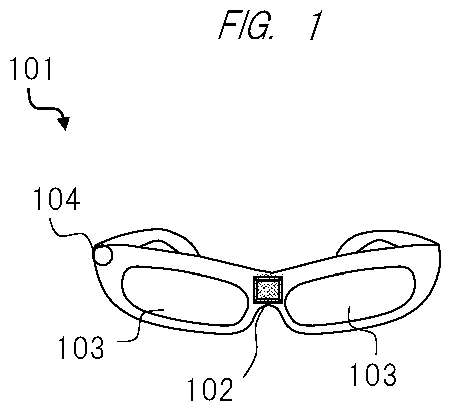
[0064]First, a configuration of the head mounted video display apparatus according to the present embodiment will be described. FIG. 1 illustrates a schematic view of a head mounted video display apparatus 101 (the distance measuring apparatus) according to the present embodiment. This video display apparatus 101 is an apparatus that measures a distance to a photographic subject.

[0065]The video display apparatus 101 includes a distance measuring sensor unit 102, video displ...

second embodiment

[0163]A different point between the present embodiment and the first embodiment is that a distance measuring sensor unit and a distance measuring unit are mounted on another apparatus.

[0164]FIG. 34 is a schematic view of a configuration of a distance measuring system that includes a head mounted video display apparatus 3405 and a calculating unit 3407. The video display apparatus 3405 (an imaging device) equipped with a video displaying function and an imaging function is connected to the calculating unit 3407 equipped with a calculating function via a communication line 3406. The calculating unit 3407 is a device that receives an image taken by the video display apparatus 3405 via the communication line 3406 described above and measures a distance to a photographic subject by using the image. Namely, the video display apparatus 3405 is an apparatus connected to the calculating unit that measures the distance to the photographic subject on the basis of an obtained image.

[0165]FIG. 3...

third embodiment

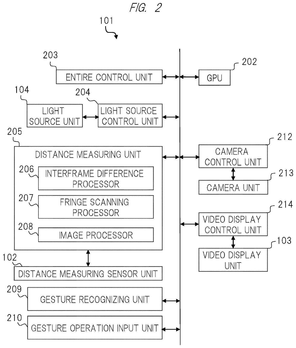
[0184]FIG. 39 illustrates one embodiment of a configuration of a video display apparatus according to the present embodiment. A difference from the configuration of the video display apparatus according to the first embodiment illustrated in FIG. 2 is that a difference region determining unit 3901 (a difference image region determining unit) is added to the distance measuring unit 205. This difference region determining unit 3901 is a part that determines an image region for which a difference is to be taken by the interframe difference processor 206.

[0185]A problem when a distance measuring apparatus according to the present invention is mounted on a head mounted video display apparatus and used will be described with reference to FIG. 40 and FIG. 41.

[0186]A photographic subject 4001 is a photographic subject at n=k−1, and a sensor image 4002 is a sensor image Si(k−1) that is outputted when an image of the photographic subject 4001 is taken by the distance measuring sensor unit 102...


PUM


Abstract

An interframe difference processor 206 generates a difference image between frames of a sensor image, and an image processor 208 generates distance information indicating a distance to a photographic subject on the basis of calculation of a difference image and a developing pattern 1101. Thus, since a video display apparatus 101 generates the difference image between the frames of the sensor image, it is possible to realize a distance measuring apparatus capable of reducing an influence of a background and generating distance information with high accuracy.

Description

TECHNICAL FIELD[0001]The present invention relates to a distance measuring apparatus, an imaging device, a distance measuring system, a distance measuring method, and an imaging method.BACKGROUND ART[0002]In order to support work in factory work and equipment maintenance work, a head mounted video display apparatus has been utilized. In many cases, a worker is holding an article necessary for objective work, and it is required that an input method to the video display apparatus is simple. Input means by a voice operation or a gesture operation has been devised.[0003]In order to realize the gesture operation, it is necessary to recognize a target object (for example, fingers or the like of a wearer) to be gestured, and to further recognize a motion of the target object. A three-dimensional recognition technique using a range image is utilized for recognition of a target object and a motion thereof. However, a small and light distance measuring apparatus is required in order to reduce...

Claims


Application Information

Patent Timeline
IPC IPC(8): G02B27/01G02B5/18
CPCG02B27/0172G02B5/1814G02B2027/0138G02B2027/014G02B2027/0178G01C3/06G02B27/0093G02B5/1876
Inventor YAMASAKI, KOJINAKAMURA, YUSUKE
Owner MAXELL HLDG LTD
Learn More