
Production Method for a Composite Fiber Component, Composite Fiber Component, Testing Method for a Composite Fiber Component, Computer Program, Machine-Readable Storage Medium and Apparatus

Pending Publication Date: 2022-02-24
ROBERT BOSCH GMBH
View PDF0 Cites 0 Cited by
  • Summary
  • Abstract
  • Description
  • Claims
  • Application Information

AI Technical Summary

Benefits of technology

[0033]The invention is based on the insight that a sensor device that is arranged in a fiber composite component and detects an acceleration, during the process of introducing a liquid matrix for producing the fiber composite component, is momentarily deflected or accelerated by the incoming flow front. In the event of detection of the acceleration in real time, this can be easily identified. The deflection or acceleration thus detected allows a conclusion to be drawn about the incoming melt (the liquid matrix). As a result, by way of the detected acceleration signal, the process parameters of resin injection (such as injection pressure, rate or temperature) or the point in time of resin injection in the overall process of the production method can be derived,

Problems solved by technology

However, said sensors leave behind traces on the end product; moreover, they may lose contact with the component, said contact being required for the sensing, owing to the shrinkage of

Method used


Image

  • Production Method for a Composite Fiber Component, Composite Fiber Component, Testing Method for a Composite Fiber Component, Computer Program, Machine-Readable Storage Medium and Apparatus
  • Production Method for a Composite Fiber Component, Composite Fiber Component, Testing Method for a Composite Fiber Component, Computer Program, Machine-Readable Storage Medium and Apparatus
  • Production Method for a Composite Fiber Component, Composite Fiber Component, Testing Method for a Composite Fiber Component, Computer Program, Machine-Readable Storage Medium and Apparatus

Examples


Example

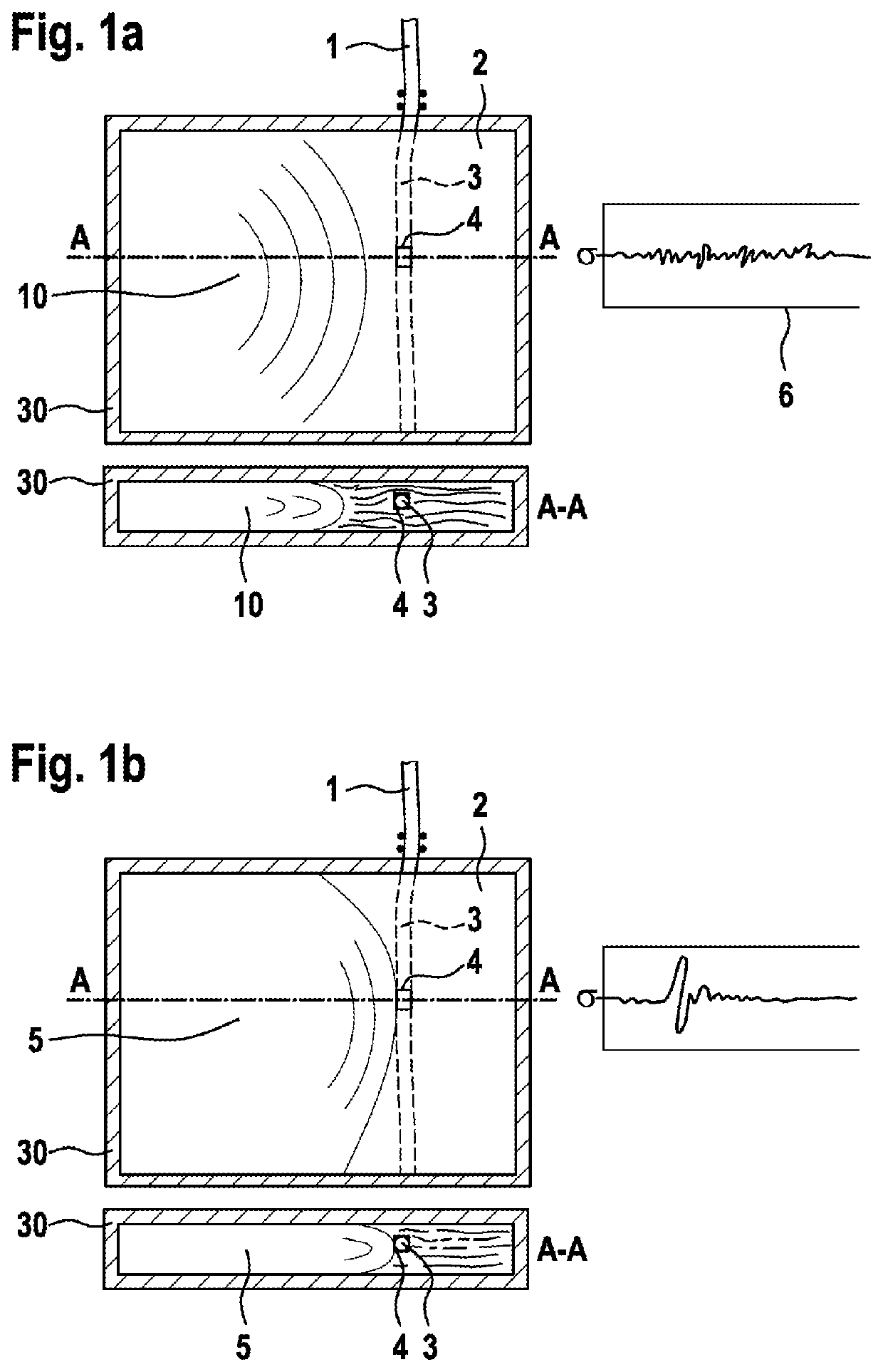
[0063]FIG. 1a shows a schematic illustration of a process step during the production of a fiber composite component according to the present invention. The illustration shows a process step during production in a Liquid Composite Molding (LCM) method of a fiber composite component comprising a sensor device 1 with a flexible circuit carrier 3 and / or a sensor module 4, said sensor device being arranged in the fiber composite component.

[0064]The process step illustrates the start of the melt flow (matrix flow) 10.

[0065]The upper part of the illustrated view is a plan view of the tool 30 (view into the interior of the tool / section through the tool). The lower part is a side view of the tool 30 on the sectional axis A-A.

[0066]A signal profile 6 of the sensor device 1 or of the acceleration detected by the sensor module 4 is plotted schematically alongside the views of the tool 30. Normal production noise can be gathered from the signal profile 6.

[0067]FIG. 1b shows a schematic illustrat...


PUM

PropertyMeasurementUnit
Flexibilityaaaaaaaaaa
Accelerationaaaaaaaaaa

Abstract

A method for producing a composite fiber component, in which a sensor apparatus having a flexible circuit carrier and/or a sensor module, in particular a micromechanical acceleration sensor module, is integrated, includes loading a tool for producing the composite fiber component with textile layers and the sensor apparatus; closing, in particular air-tight sealing, of the loaded tool and compressing the textile layers and the sensor apparatus; introducing a liquid matrix, in particular a resin, in particular a pure resin, into the sealed tool to produce the composite fiber component; detecting, in particular in real time, an acceleration relative to the introducing and/or sealing by means of the sensor apparatus and/or the sensor module of the sensor apparatus; and deriving and/or evaluating a process parameter of the production method depending on the detected acceleration.

Description

[0001]The present invention relates to a production method for a fiber composite component, a correspondingly produced fiber composite component, a test method for a correspondingly produced fiber composite component, a computer program and machine-readable storage medium corresponding thereto, and also a device corresponding thereto.PRIOR ART[0002]WO 2018 / 069066 A1 discloses a method for arranging a number of micromechanical acceleration sensors on or in a plastics component, in particular a fender, and a corresponding plastics component, in particular fender.[0003]In step A of the method, the micromechanical acceleration sensor is fixedly positioned into or onto a flexible circuit carrier, wherein the micromechanical acceleration sensor is contacted with an integrated conductor track structure of the flexible circuit carrier.[0004]In step B of the method, at least regionally the micromechanical acceleration sensor and the flexible circuit carrier are arranged onto or into the plas...

Claims


Application Information

Patent Timeline
IPC IPC(8): B29C70/70G01P15/08G01N3/08B29C70/48
CPCB29C70/70B29C70/48G01N3/08G01P15/08B29C70/443
Inventor KLEIN, LINDA
Owner ROBERT BOSCH GMBH
Learn More