Control cam assembly for controlling a movement of a furniture part

Active Publication Date: 2022-02-24
JULIUS BLUM GMBH
View PDF7 Cites 4 Cited by
  • Summary
  • Abstract
  • Description
  • Claims
  • Application Information

AI Technical Summary

Benefits of technology

[0006]It is an object of the present invention to propose a control curve arrangement mentioned in the introductory part, thereby avoiding the above-discussed drawbacks.
[0008]In other words, the control curve arrangement includes at least one timing element operative between the base member and the switch element. The timing element is configured to position the base member and the switch element relative to one another such, after the insertion movement of the pressure portion into an end position corresponding to a closed position of the movable furniture part in a mounted condition, that an outward movement of the pressure portion can be prevented in the opposite direction. Only after a period of time specified by the timing element, the base member and the control curve are again positioned to one another such that a movement of the pressure portion into an extended position can be made possible.

Problems solved by technology

Here, there is also the problem that the ejection device will inadvertently be triggered, caused by an undue high closing speed of the door wings, and the door wings will immediately be ejected back in a direction of an open position.

Method used


Image

  • Control cam assembly for controlling a movement of a furniture part
  • Control cam assembly for controlling a movement of a furniture part
  • Control cam assembly for controlling a movement of a furniture part

Examples


Embodiment Construction

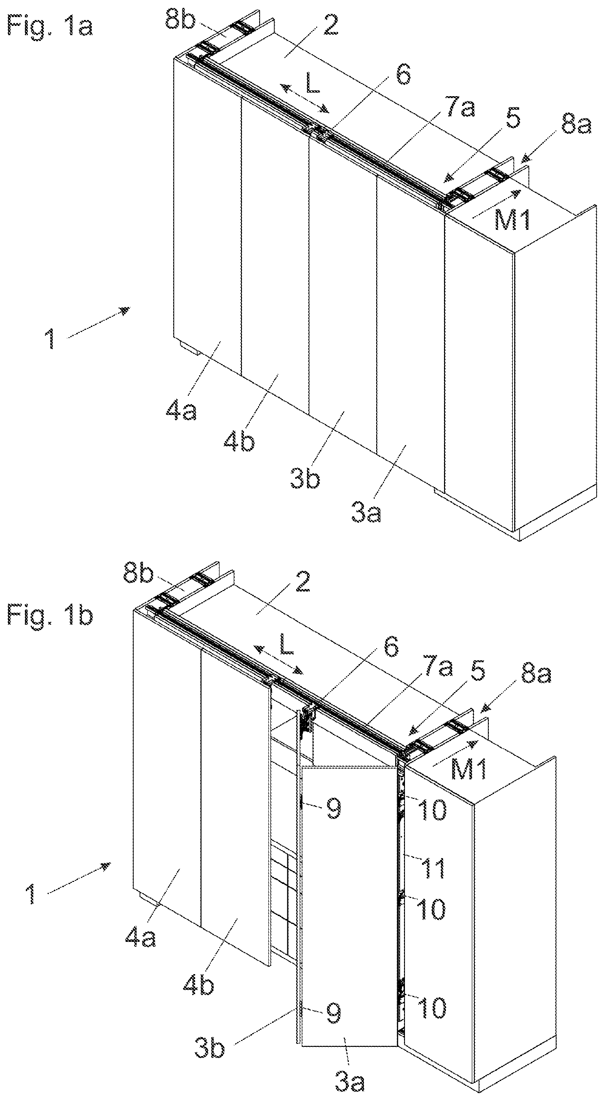
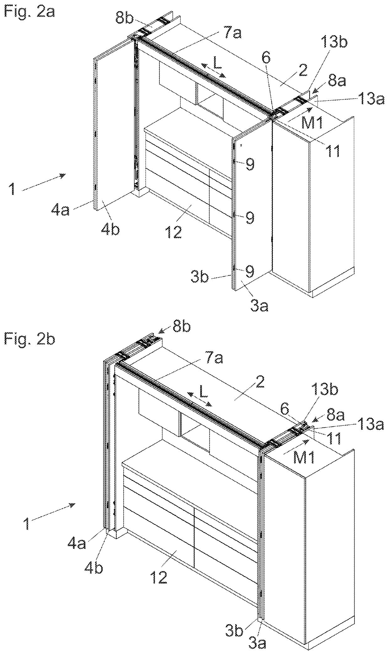
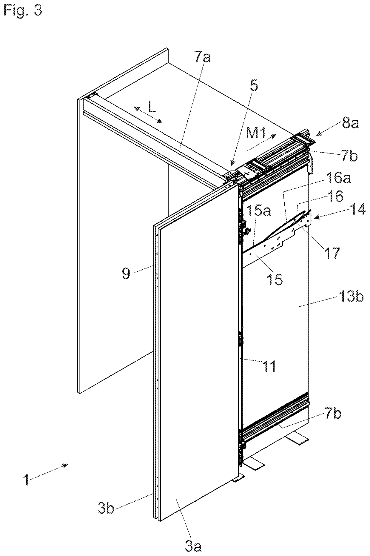
[0030]FIG. 1a shows a perspective view of an item of furniture 1 comprising a furniture carcass 2 and panel-shaped furniture parts 3a, 3b; 4a, 4b configured to be movable relative to the furniture carcass 2. The furniture parts 3a, 3b, 4a, 4b are movably supported by a guide system 5 between a first position, in which the furniture parts 3a, 3b, 4a, 4b are aligned substantially coplanar to one another, and a second position, in which the furniture parts 3a, 3b, 4a, 4b are aligned substantially parallel to one another. The furniture parts 3a, 3b, in the second (parallel) position, can be inserted in a first movement direction (M1) into a lateral receiving compartment 8a of the furniture carcass 2, whereas the two other furniture parts 4a, 4b, in a parallel position to one another, can be inserted into a further receiving compartment 8b. The functionality will be explained in the following with the aid of the furniture parts 3a and 3b, and the same explanations apply to the other furn...


PUM


Abstract

A control curve arrangement including a base member having a first control curve, a switch element separate from the base member and having a second control curve, a pressure portion to be displaceably supported along the first control curve and the second control curve, and a spring device for applying a force to the pressure portion. The pressure portion, in the first operating position and in a first movement direction, is displaceable along the second control curve of the switch element. The pressure portion, in the second operating position and in a second movement direction opposite the first movement direction, is displaceable along the first control curve of the base member. A timing element is operative between the base member and the switch element, and the switch element can be transferred from the second operating position into the first operating position by the timing element in a time-delayed manner.

Description

BACKGROUND OF THE INVENTION[0001]The present invention relates to a control curve arrangement for controlling a movement of a furniture part movably-supported relative to a furniture carcass. The control curve arrangement includes a base member having a first control curve, and a switch element separate from the base member, the switch element having a second control curve. The base member and the switch element are movably-supported relative to one another between a first operating position and at least a second operating position. A pressure portion is configured to be displaceably supported along the first control curve and the second control curve, and a spring device applies a force to the pressure portion. The pressure portion, in the first operating position and in a first movement direction, is configured to be displaceable, at least over a region, along the second control curve of the switch element. The pressure portion, in the second operating position and in a second mov...

Claims


Application Information

Patent Timeline
Patent Type & Authority Applications(United States)
IPC IPC(8): E05F1/10E05D15/58E05F3/20
CPCE05F1/1041E05D15/58E05D2015/586E05Y2900/212E05F3/20E05F1/16E05D15/264E05Y2201/212E05Y2201/638
Inventor MEUSBURGER, MARCIRGANG, MARKUSRUPP, MATTHIAS
Owner JULIUS BLUM GMBH
Why Eureka
Try Eureka